It is indeed a possibility, but of course as there are no free lunches, the negative swing would be further reduced.Furthermore, the increase in distortion could be compensated by doubling R4 and R12 in your schematic.
And if you try to reduce the current in R4/R12 in the same proportion, the transconductance of the input pair would be reduced by the same amount, canceling the gain benefit
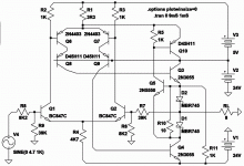
Again, bases of Q5Q6 (LP) should be -20 rail.
To allow the full negative output swing.
Cascode supply then providing -22.5.
But why some bizarre voltage like 2.5?
3.3V or 5V warts are more easily scavenged.
The original pair there also had a short tail R5
(OP) that Elvee said necessary for stability.
Somehow in the rush we forgot that?
To allow the full negative output swing.
Cascode supply then providing -22.5.
But why some bizarre voltage like 2.5?
3.3V or 5V warts are more easily scavenged.
The original pair there also had a short tail R5
(OP) that Elvee said necessary for stability.
Somehow in the rush we forgot that?
Last edited:
I've no idea what that means, due to lack of a schematic. The idea sounds interesting yet vague. Connect where?The output cannot swing very low with that cascode in the way. Have you considered the existing negative rail for cascode base? You would have to provide an extra negative rail for circlophony. But it needn't be anything elaborate since the common mode is strongly controlled by quadrature anyway, a 5v wart might do.
Again, could you show your idea on schematic? Even a sketch would do fine. Please, something to see instead of confuse.Again, bases of Q5Q6 (LP) should be -20 rail. To allow the full negative output swing. Cascode supply then providing -22.5. But why some bizarre voltage like 2.5? 3.3V or 5V warts are more easily scavenged.
Well, I looked up the "OP" (post #1) Original Post's R5 and I didn't omit that resistor on any schematic posted. Therefore, what???The original pair there also had a short tail R5 (OP) that Elvee said necessary for stability. Somehow in the rush we forgot that?
circlophone
How would a printed circuit board look like. I did design 40 years ago but then stopped and now my knowledge is not even there any more . Daniel sorry but I misread the number of your output devices when I did ask if those output devices were able to stand this abuse!
Krokkenoster is a DNA mixture of all species! Before I got injured I worked on all kinds of lift truck sort of "Jack of all trades"
HEAR HEAR!!!!!Then it'll just be weird and everyone will immediately look for something else to build.
Although it is a good idea.
How would a printed circuit board look like. I did design 40 years ago but then stopped and now my knowledge is not even there any more
. Daniel sorry but I misread the number of your output devices when I did ask if those output devices were able to stand this abuse!Krokkenoster is a DNA mixture of all species! Before I got injured I worked on all kinds of lift truck sort of "Jack of all trades"
Cease your panic. LP was 1059, no reference intended to any of yours.Well, I looked up the "OP" (post #1) Original Post's R5 and I didn't omit that resistor on any schematic posted. Therefore, what???
Keantoken's LP schematic appears to omit equivalent function of R5 (OP).
Read 1062 again, I was specific which reference designators were LP and OP.
1062 also answered your question regarding proper use of the extra rail.
I will draw for you when I get around to it, Patience...
Last edited:
Daniel,HEAR HEAR!!!!!
How would a printed circuit board look like. I did design 40 years ago but then stopped and now my knowledge is not even there any more
Krokkenoster is a DNA mixture of all species! Before I got injured I worked on all kinds of lift truck sort of "Jack of all trades"
Thank you for the info sent to me I appreciate it.Before anyone develops a drawing withdrawal anurism...
Here we can swing an output within 1.4V of either rail.
Because this cascode's reference drop isn't in the way.
No other point was intended, so ignore everything else
that might be weird about this circuit. Its not finished.
Here we can swing an output within 1.4V of either rail.
Because this cascode's reference drop isn't in the way.
No other point was intended, so ignore everything else
that might be weird about this circuit. Its not finished.
Attachments
Basically, I hate anything resembling multiple supplies.
I have designed amplifiers or variable lab supplies amongst other things, but I always managed to get decent performances without this kind of prop, even high voltage supplies with full I/V control down to zero.
The plain vanilla Circlophone swings to within 1.5V of either rail without any artifice, and I think it would be a pity to depart from that philosophy.
Basically, I hate anything resembling multiple supplies.
I have designed amplifiers or variable lab supplies amongst other things, but I always managed to get decent performances without this kind of prop, even high voltage supplies with full I/V control down to zero.
The plain vanilla Circlophone swings to within 1.5V of either rail without any artifice, and I think it would be a pity to depart from that philosophy.
Then we ought to drop this non-folded cascode nonsense instead.
We can't swing both rails with that added piece of junk in the way,
there is no support for adding the wart rail, to shift a cascode out
of the picture. I never saw what cascode supposed to fix anyhow...
Original circlophone satisfied all cometary collision requirements.
Some of the random "improvements" thrown at it of late, do not.
I rarely post anymore, only cause I can't come up with anything
stable that outperforms it. And not for lack of trying...
Last edited:
The Circlophone is undoubtedly perfectible and improvable, just like anything else.
And I do not not mean absolute improvement, because by adding more components, it is always possible to improve performances, but that is not what I am interested in.
What I mean is a better performance to complexity or resource ratio: a rearrangement of the existing components for instance.
The compensation scheme has in my opinion the most potential for improvement.
Kean has made a brave attempt in this direction, but not a completely convincing one so far.
Oh, don't you worry, I'll bury circlophone with something revolutionary if you
don't top your own masterpiece sooner. I wouldn't put it past you to have a
few more awesome surprises under development.
I just need to get past this terrible stability barrier thats holding me back.
Almost tempted to force a known oscillation, just to claim that it was part
of the plan all along, and not something uninvited I couldn't control.
Last edited:
I think that the super important thing to remember about Circlophone is its live sound character, which, to me, is very much the reason to use it instead of a blameless/standard topology. Whatever modifications or refinements we make, it seems good or even important to retain the "sounds live" benefit. I do not know the cause of the unique characteristics.
What I've got prioritized is:
1. Attempt lower current in the feedback shunt resistor, such as using 1K instead of 470R to see if it is possible to push the efficiency peak higher than the audio band rather than landing at 8khz sometimes, and seemingly better to prevent/block a treble problem instead of solving it by parts swapping, but parts swapping is the current solution at this time.
2. The BC560C buffer arrangement that the simulator claims just makes stuff run a little bit better despite some minor variances in compensation or not. Well, I haven't soldered that up yet because I've been working on line level stuff and catching up on the roundtoit list. BC560C's are not rare so there's no shame in requiring them, and it is looking like a good idea.
3. Get a higher powered circlophone to run as well as the low powered example in post 1 (because higher power can push a wider variety of speakers). Currently a transistor turns off on the higher powered versions and there is sometimes but not always a frequency response or treble harmonic errata (I don't know which) on the higher power versions. Perhaps that problem will disappear after exploring 1 or 2 above?
The more I learn, the more questions I find.
Hello,
I tried to simulate several variations of the circlophone driving ESL speaker with a 1:150 step-up transformer. It shows the idle power of the upper output transistor (MJL21194) is 2.8 Watt, but the lower (negative) side one dissipates 308 W. If i change the load to a resistor of 8R, the iddle power are 5.9 and 6.4 W respectively. A load resistor of 3R gives almost the same results.
Can someone point me in the right direction to solve this ?
With circloMOS i'm getting I can get much reduced iddle power dissipation of the O/P stage, but the distortion is far inferior.
Edwin
(i could post the LTspice file if someone is interested).
That would be the first thing to do....(i could post the LTspice file if someone is interested).
That would be the first thing to do....
Ok Elvee, here it is.
For your information, the amp is supposed to be driven by a miniDSP board mith Zout of 560R, and Vrms max = 0.9V. For some configurations the headroom seems to be rather limited. The ESL will be crossed over to a subwoofer at 120 Hz and the DSP will need to boast +/- 8dB at 160 Hz.
The step-up should be able to give a Vpk of 3.5KV.
Thanks for looking in to this.
Edwin
Attachments
Some transistor models are not included, so I couldn't run the simulation, but anyway the likely cause of the problems is the lack of a DC blocking capacitor in the output, and/or a low/absent winding resistance for the transformer.
I wasn't able to track the actual series resistance used by the simulation: I saw it equaled Rip, which then equaled Ris, but then I lost the track.
Even if there is a finite series resistance, it is probably not a good idea to drive the transformer directly: normally, this type of transformer is ungapped and has a high permeability, and the winding resistance is low.
All this means that even a negligible output offset voltage will be sufficient to saturate the core.
It will also cause a high dissipation in one of the OP transistors, because the amplifier will try to impose this OS voltage to a low resistance.
Try inserting a large cap in the output, this should fix the problem.
BTW, making R23 ~=0 will probably cause problems. Even if they don't appear in the sim, the reality will be less forgiving.
- Home
- Amplifiers
- Solid State
- ♫♪ My little cheap Circlophone© ♫♪