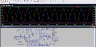
When you apply non-default minor parameters to a component, you should show it explicitly when you share a graphic-only attachment on the forum, Otherwise, it is completely impossible to guess (and even then, you have to look into the component in question, that's not obvious)I got these values worked out from adding a resistor series to C2 to represent a lossy imperfect cap. The sim freaked out with instability as usual, whenever that resistor is present.
Previously indicated at post 1039, there was indeed a temporary torture test, and after achieving the higher quality of hardened centerpoint values, all parts were re-checked and shown at default prior to posting.
As shown, it does not contain any non-default minor parameters. But it will resist them.
As shown, it does not contain any non-default minor parameters. But it will resist them.
Last edited:
OK, it should be fine then.Previously indicated at post 1039, there was indeed a temporary torture test, and after achieving the higher quality of hardened centerpoint values, all parts were re-checked and shown at default prior to posting.
As shown, it does not contain any non-default minor parameters. But it will resist them.
I do not get similar results, but I use the original Circlophone parts, that's maybe what causes the divergence.
The only thing that remains to do is to validate the circuit with a physical prototype, and check the improvements do indeed materialize.
circlophone
 Ok I was looking for a circuit that could give me a reasonable output (20 Watts or so) for home use. How long will those little output transistors last if they get driven this hard to their maximum? Fatter transistors are not all that more expensive and WILL last a lot longer.
This is exactly what I was thinking! Did you guys build this extremely invoved circuit or was it just theory? I discovered that the more simpler a thing the better it perform at the end.OK, it should be fine then.
I do not get similar results, but I use the original Circlophone parts, that's maybe what causes the divergence.
The only thing that remains to do is to validate the circuit with a physical prototype, and check the improvements do indeed materialize.
Ok I was looking for a circuit that could give me a reasonable output (20 Watts or so) for home use. How long will those little output transistors last if they get driven this hard to their maximum? Fatter transistors are not all that more expensive and WILL last a lot longer.Here's a link to the build thread.This is exactly what I was thinking! Did you guys build this extremely invoved circuit or was it just theory? I discovered that the more simpler a thing the better it perform at the end.
http://www.diyaudio.com/forums/soli...tion-parts-accessories-beginner-friendly.html
Refer to this schematic for your 20 watts (actually 27 watts):
http://www.diyaudio.com/forums/atta...es-beginner-friendly-circlophone-original.gif
If this looks overly complex, try an LM1875 for good practice.
P.S.
To quickly rough estimate, with 57% of datasheet dissipation watts for AC (Music or PWM) output, I just pulled up the MJE3055 datasheet, saw 75 watts from OnSemi, used the calculator with a crude *0.57 and got ~43 watts into 8 ohms. SO, the smallest of the 3055's generously exceeds your 20w requirement by approximately 215%. A problem was where???
It is true that the MJL21194 in the simulations with 4 ohm speakers does not meet this criteria (it is "almost"); however, it is also true that some small rail pulldown (a minor volt or two) will occur at this point, thus meeting the safety estimate requirements in real life unless your capacitor bank is gigantically too big so that rail stiffness erroneously lasts longer than SOAR test timeframe, but that sort of error is rare due to the expense of causing it, so really, the MJL21194 should work fine if your rails are 35+35vdc.
The power output niche obliterated by the hi-fi LM1875 projects is why I didn't show voltage lower than 35+35vdc on the sims, and the output device selections is why I didn't show voltage higher than 35+35vdc on the sims. Of course we could do higher voltage if it was known that 8 ohm speakers are used. We're actually only using a fraction of the MJL21194's capacity.
And, the strong MJ15003 is available! These are not puny.
Last edited:
Well, to me it looks like none of it is an overdo (let's check that again) and all of it is better than the usual strong miller comp or similar heavy-handedness. What looks familiar is that most good hi-fi amplifiers usually have a dozen small and transparent corrections instead of a big fell swoop. Although it is important that all of the corrections are small/transparent to audio, it seems even more important that all would be different so that they can't add up to any peak in the sonic signature. What do you think?The compensations being applied here are becoming, shall I say, multiplicitous... Though if that ends up with a better result, I think it's pretty cool.
That was my impression, that one half presented a different Bode than the other?
I kinda deviated towards a circlopony in complimentary symmetry, as-if that were
some kinda magic bullet to make both Bode the same. Now even with perfect open
phase, both differential halfs are equally unstable in .tran . I got rid of my input pair
Miller by neutralization, and there probably lies the greater part of my folly.
Neutralizaton on the top side only works when the tail isn't messing with the class
Aness of it all from the bottom side...
Last edited:
The output cannot swing very low with that cascode in the way.
Have you considered the existing negative rail for cascode base?
You would have to provide an extra negative rail for circlophony.
But it needn't be anything elaborate since the common mode is
strongly controlled by quadrature anyway, a 5v wart might do.
Have you considered the existing negative rail for cascode base?
You would have to provide an extra negative rail for circlophony.
But it needn't be anything elaborate since the common mode is
strongly controlled by quadrature anyway, a 5v wart might do.
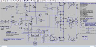
VAS, which VAS? As-if it were nailed down to one location.
The one that pulls up against constant current for half the cycle
Or the entirely other one that pulls down against constant current
in the opposing half cycle?
If the common mode loop is disabled, you have no less than five
transistors that could be VAS Q 5,6,7,8,16...
The one that pulls up against constant current for half the cycle
Or the entirely other one that pulls down against constant current
in the opposing half cycle?
If the common mode loop is disabled, you have no less than five
transistors that could be VAS Q 5,6,7,8,16...
Last edited:
I havn't seen a schematic of this thread with BC560, at least not lately.
Also havn't seen where I can pinpoint a solitary VAS. Cascode voltage
could mean anything outside the context of a specific schematic and
reference designator that you have neglected to reference.
It certainly makes no sense in the default context of the most recently
posted schematic #1049. Please post your current schematic or link to
past required to make sense of your statement.
Last edited:
I don't know what it means without seeing the difference between two options. Could you post a schematic, so I could see?The output cannot swing very low with that cascode in the way. Have you considered the existing negative rail for cascode base? You would have to provide an extra negative rail for circlophony. But it needn't be anything elaborate since the common mode is
strongly controlled by quadrature anyway, a 5v wart might do.
That is doable. See attachment.I havn't seen a schematic of this thread with BC560, at least not lately.
Attachments
That was a fluke. Hopefully someone would use BC550 when it comes time for the NPN. Point taken--BC560 vas did look a bit odd. So, anyway. . .I love the way you use BC560 as both an NPN and PNP.
How is your demonstration schematic coming along to explain that extra negative rail to fix the cascode? I just can't quite imagine it from the words, but a schematic or even a sketch would be great.kenpeter said:The output cannot swing very low with that cascode in the way. Have you considered the existing negative rail for cascode base? You would have to provide an extra negative rail for circlophony. But it needn't be anything elaborate since the common mode is strongly controlled by quadrature anyway, a 5v wart might do.
Last edited:
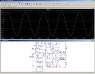
I tested the idea. It seems to work, but with a THD figure approximately doubled, which is consistent with the degeneration of 4 junction resistances in the VAS, compared to two in the regular Circlophone.Actually, using PNP for Q3 and Q4 is an interesting idea. This would reverse frontend and servo phase, making it an involving change.
Attachments
- Home
- Amplifiers
- Solid State
- ♫♪ My little cheap Circlophone© ♫♪