Thanks!
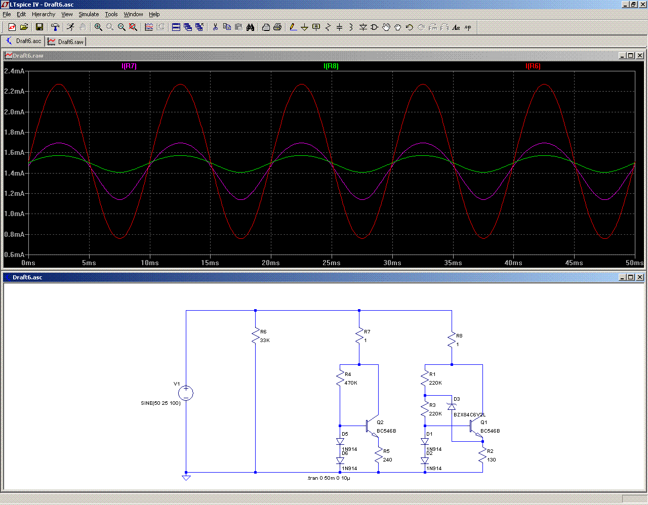
Since it is the RC value that needs investigated further, I just did some homework. Given a variety of ~3.3v glass bead zeners in the range, 1/5thw, 1/4w and 1.3w, a series pair of any measured close to the cap value of 82p, and I cross checked the DMM with real ceramic caps for confirmation. Probably 100p for simulator would work fine. But I do not know the loss figure or dynamic behavior.
No idea what the dynamic RC value would be.
Can you rough estimate the capacitance and resistance while the Circlophone is running from a single rail source, such as a computer?
Thank you for this excellent news that D12 and D13 aren't especially harmful. They are helping to make the offset trimmer superfluous in a greater number of cases because of 1/3rd volt farther away from misfires that cause ~250mv DC offset bounce. Boosting the misfire tolerances up to avoid installing the offset trimmer is more attractive for low components count builds. Simply put, adding D12 and D13 allowed me to remove the trimmer, remove the feedback kludge and return the NFB cap. . . and get unstuck.
P.S.
Some of what you're seeing makes the difference between a power amp's features versus an integrated amp's features--mitigating source problems and variances. Indeed if that can be done with just 2 transistors and a few simpler parts, then it can remain a low component count elegance.
Goal: Reduces computer & speaker damaging surges (and works in practice).I see no other problem than the one already mentioned by Kean: the non-linearity of the low voltage zeners, both in resistance and capacitance.
Since it is the RC value that needs investigated further, I just did some homework. Given a variety of ~3.3v glass bead zeners in the range, 1/5thw, 1/4w and 1.3w, a series pair of any measured close to the cap value of 82p, and I cross checked the DMM with real ceramic caps for confirmation. Probably 100p for simulator would work fine. But I do not know the loss figure or dynamic behavior.
No idea what the dynamic RC value would be.
Can you rough estimate the capacitance and resistance while the Circlophone is running from a single rail source, such as a computer?
Goal: Reduces "offset bounce" problem (and works in practice).BTW, D12 and D13 are superfluous
Thank you for this excellent news that D12 and D13 aren't especially harmful. They are helping to make the offset trimmer superfluous in a greater number of cases because of 1/3rd volt farther away from misfires that cause ~250mv DC offset bounce. Boosting the misfire tolerances up to avoid installing the offset trimmer is more attractive for low components count builds. Simply put, adding D12 and D13 allowed me to remove the trimmer, remove the feedback kludge and return the NFB cap. . . and get unstuck.
P.S.
Some of what you're seeing makes the difference between a power amp's features versus an integrated amp's features--mitigating source problems and variances. Indeed if that can be done with just 2 transistors and a few simpler parts, then it can remain a low component count elegance.
Last edited:
2N5551, 2N5401 failures documented.
Please don't install OnSemi 2N5551.
The OnSemi 2N5551 from Sanyo's China fab plant (Digikey stock) may have HFE 30 or HFE that falls unexpected with current, plus sometimes half speed, and may fail in service. They're even worse than fakes. The same may or may not happen with Moto-China (today's Motorola), so those need checked too, although the usual problem with new Motorola parts is the less obvious issue of noise performance that varies.
Solution:
Fortunately, there are many brands of 2N5551, without a problem:
Philips, CentralSemi, KEC, Fairchild, NXP, and more, do still have normally functioning 2N5551's and 2N5401's (and other similar parts).
NXP website search also documents some substitutes, since the 2N5551 is from a large family of similar devices.
Last edited:
How this amp sounds against the LM3886 and F5?
And what the total estimated cost of the amp with parts?
I built some Gainclones including balanced mode bridged versions. My Circlophones surpassed all of them in terms of clarity, background noise level, bass, vocal performance and dynamics although my Gainclones were very good performers.
The cost is determined by output device selection (which varies) and PCB build skills in my opinion. (I assume you already have a Power Supply unit.)
F5, I don't know. For TV use, I don't know. For music replay, the Circlophone can beat the LM3886.How this amp sounds against the LM3886 and F5?")
It could be about $8 USD more than LM3886. But, I think that a Circlophone is "more" amplifier.And what the total estimated cost of the amp with parts?
P.S.
Circlophone build thread: http://www.diyaudio.com/forums/soli...tion-parts-accessories-beginner-friendly.html
Last edited:
Audiometric, Offset bounce, hammer-pillow-thumb, and current
I was looking at the offset bounce issue with a new perspective, and that is audiometrics. For offset bounce to occur, D10 and/or D11 switch on to the bass beat when not all of the bass can travel the 470u. Well, a ballpark audiometric value for C3 (same value that would keep the diodes off) is far too large to consider; however there are several alternatives.
Simulations of Circlophone consistently show some benefit to buffering the input in several ways. One day, not long ago, I was wondering about these added transistors that effectively serve as a pillow between the hammer and the thumb, and if instead we could reduce the size of the hammer by reducing the current a little bit, and then not need any added transistors.
Reducing the current can be done with R16, R19 to 1.2k or higher figures. It seems to answer both of the above questions; but, as usual, there is the new question if the fix is suitable?
Of course I want the buffer, but I'm doing a "back to basics" review for the dual purpose of possibly running without the buffer and to make the compensations a lot easier. There's something "off" with the tolerances and I don't want to cover that up without first discovering the source. After reading the whole thread again, I find a few things that take priority. First, the audiometrics are so powerfully off the mark that D10, D11 have been damaged by overcurrent surges on a few builds. This area is also the source of the offset bounce.
One possible option is to fix the audiometrics with 470u~1.5k vs 56k so that the NFB cap is then apparently big enough so that D10, D11 accidents are rare rather than frequent.
If audiometrics are not repaired, I we chould change to a triple chain of BAT85 for 0.9v, and even 3 of those makes a LOT less noise than one 1N4148. However, audio quality is not the only concern. This area breaks small diodes from over-current, and then it is difficult to figure out what went wrong. Eventually, not fixing the audiometrics then requires something very much like this: 4.7R~FR\\FR~FR\\FR, a series pair of quiet 0.45v soft fast silicon diode clippers series to 4.7R, giving the approximately the 0.9v tolerance that the circuit seems to need, in combination with enough current capacity to withstand error conditions, still a lot more quiet than 1n4148's, and the resistor is added to the clipper for allowing the NFB cap to compete with the diodes until the loss at cap roll off exceeds 4.7R (a lot lower pitch). In this combination method of postponing the diode switch-on, an undersize NFB cap (470u~470R) may be used without turning the bypass diodes into a problem.
Since we've already exploded some 100ma diodes, we might want to consider that BC556B has 100ma maximum surge rating, and that BC327-40, with 800ma surge tolerance might be a safer bet for longevity of the input pair.
I'd rather use audiometric sized feedback-shunt area (470u~1k5 vs 56k) removing error instead of using high current parts to withstand error. But of course we could do both, since the replacements are excellent quality low noise devices.
P.S.
Previously, we tried to automate D8, D9 by replacing them with a single transistor resulting in dull audio and compensations that quit working--the last time I tried this, there was strong HF distortion as if the feedback capacitor was removed. This needs tried again but a bit closer to the rail or with a different reference point.
Perhaps we need to automate R21 prior to any other mod? Elvee proposed using one of these ccs for replacing R21:
At the time, I thought it was a complicated way to make an inconvenient resistor; but, now I think it could really help, since hitting a moving target of the rails bouncing with the speaker is a job for one of those ccs. Right? And are those 1n914's switching or are they simply on?
Last edited:
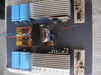
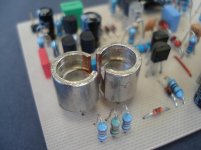
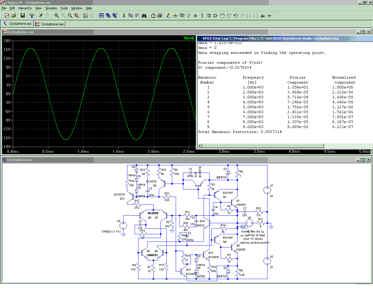
Miniature Circlophone spotted! Thanks!
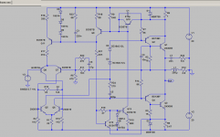
With 20+20VDC, your R21 at 33K should probably be closer to 27K. Your two zeners, 12v+12v=24v, probably sounds fantastic; however, it should technically be just 1 of 1w 20v zener so that the 2N3019's are both running at the same temperature. At this low voltage, you can show the outputs as MJE3055, which are in more convenient TO220 size packages. BC560C's can be used for input pair. The RF blocking +input RC is missing. R20 is fascinating because I haven't seen it before. The input load is missing. The approximately 150u power caps are missing. Either the NFB cap or the offset trimmer accessory, is missing.
With 20+20VDC, your R21 at 33K should probably be closer to 27K. Your two zeners, 12v+12v=24v, probably sounds fantastic; however, it should technically be just 1 of 1w 20v zener so that the 2N3019's are both running at the same temperature. At this low voltage, you can show the outputs as MJE3055, which are in more convenient TO220 size packages. BC560C's can be used for input pair. The RF blocking +input RC is missing. R20 is fascinating because I haven't seen it before. The input load is missing. The approximately 150u power caps are missing. Either the NFB cap or the offset trimmer accessory, is missing.
Last edited:
Compensation optimizations
Elvee, have you any basic rules to determine suitable compensation value ranges to be sure about circuit is not that far from its actual performance? I mean, I need such an advice like "increase/decrease these compensation (R and C respectively) values if these transistors contain this feature". I tend to use variety of transistors in terms of Ft, gain, noise level etc. and I'm curious about my amp's actual performance.
Thanks.
The compensations have been optimized for 2N3055's, and if you use very different transistors, there might be some slight differences in the dynamic behaviour: with 2N3772 or 2N6259's, the slew rate is somewhat decreased.
Elvee, have you any basic rules to determine suitable compensation value ranges to be sure about circuit is not that far from its actual performance? I mean, I need such an advice like "increase/decrease these compensation (R and C respectively) values if these transistors contain this feature". I tend to use variety of transistors in terms of Ft, gain, noise level etc. and I'm curious about my amp's actual performance.
Thanks.
It is practically impossible to give general rules: there are too many factors to take into account: the VAS, drivers and OP can have Ft's and capacitances varying widely (in a ratio exceding 100:1 for the OPs), and each combination will have its own optimal values.
By contrast, the DC conditions are easy to compute, and the noise has no influence on components value.
I recommend you make a test, and if you see something is wrong you can try to correct it by altering the values.
Normally there is no risk of instabilities causing destruction (don't connect a speaker until everything is fine though)
I have simulated Darlington output version respecting the schematic at post #16. I used TIP142 and BDV65B libraries that i found at internet. I measured collector currents of Q5 and Q6 servo transistors and simulation shows 20-40 pico amperes per transistor besides 10-13 mA in standard version. If those such low current levels in simulation are realistic, I think that servo transistors must behave problematic in these conditions. For example, Ft of Q5 and Q6 must drop to excessively low levels.
I adapted my CFP pcb to standard version and I plan to share without attempting to build it. I'm working on a simplistic darlington version pcb and my concern mentioned above is related with this work.
Note: I will check the schematic again immediately to be sure for 120R's (R3 and R6) are there.
I adapted my CFP pcb to standard version and I plan to share without attempting to build it. I'm working on a simplistic darlington version pcb and my concern mentioned above is related with this work.
Note: I will check the schematic again immediately to be sure for 120R's (R3 and R6) are there.
Last edited:
I have simulated Darlington output version respecting the schematic at post #16.
Did you notice that this schematic is completely upside down? Supplies are reversed, transistor polarities are reversed, etc
If you missed one thing, nothing will work just like the symptoms you describe.
Alternatively, post your asc file for a check.
Did you notice that this schematic is completely upside down? Supplies are reversed, transistor polarities are reversed, etc
If you missed one thing, nothing will work just like the symptoms you describe.
Alternatively, post your asc file for a check.
I got figure it out. Input LTP alignment was wrong. After correction, measurements became realistic. I attached asc file anyway. When I use on-semi bdv65b spice model distortion level becomes remarkably high comparing TIP42 model below. Maybe it's related with insufficient model. I appreciate to take your opinion about on-semi BDV65B model file, because I plan to use authentic Philips BDV65B's in this project.
I'm also trying to find a good alternative for PNP servo transistors. Despite lack of Philips BD140's official CoB value, it seems to best to use it under 80V power supply conditions. For above power supplies, 150V/200mhz 2sa1360 seems fit despite its extremely low output capacitance (2.5 pF) if it adequate to solder a 8-10pF capacitor to its C-B legs.
Attachments
Last edited:
Strange things happen with this model: it looks like half transistor, half darlington. Perhaps it has to do with the integral B-E resistors (real or simmed, I have no idea).When I use on-semi bdv65b spice model distortion level becomes remarkably high comparing TIP42 model below. Maybe it's related with insufficient model. I appreciate to take your opinion about on-semi BDV65B model file, because I plan to use authentic Philips BDV65B's in this project.
Shown below is the Vbe of the Op transistors.
We see that during their theoretically inactive part of the cycle, only the input transistors must be active because the Vbe is at 0.55V, with an Ic of 190mA.
Why not, that depends on the ratio of internal resistors.
But when the current becomes larger, anomalies appear: when the input transistor's current is insufficient, the voltage should jump to the next Vbe to catch up.
But what we see here is an arch of sinusoid, following linearly the output current.
This is quite strange and unexpected.
If the real component actually behaves like that, the THD will effectively jump to 0.025%. But I suspect that the parameters of the (probably single) transistor have been manipulated to look like a darlington, and in this case the approximation causes the strange behavior.
Many video output transistors could fit, some BF4xx or BF8xx. If their capacitance is too low for self compensation, an additional cap could be added.I'm also trying to find a good alternative for PNP servo transistors. Despite lack of Philips BD140's official CoB value, it seems to best to use it under 80V power supply conditions. For above power supplies, 150V/200mhz 2sa1360 seems fit despite its extremely low output capacitance (2.5 pF) if it adequate to solder a 8-10pF capacitor to its C-B legs.
The 2N5401 could probably also be used.
Attachments
- Home
- Amplifiers
- Solid State
- ♫♪ My little cheap Circlophone© ♫♪