 Hello Everyone
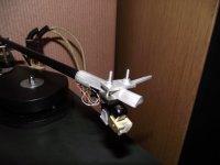
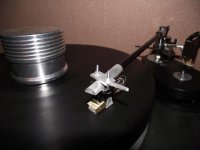
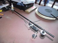
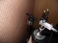
Here is a method of suspending the weight by a thread (7lb fishing line), decoupling it and enabling correct azimuth-sounds pretty esoteric eh?
It took 5 minutes to fabricate. The whole affair is suspended on a grommet (the ones used to protect electric cables as they pass through a metal casing) pushed onto the stub. The fishing line simply loops over this and then passes down to the weight which hangs from this.
There is enough contact between grommet and fishing line to ensure azimuth is correct and remains in place.
NEXT QUESTION: Is it worth doing?
ANSWER: Maybe/maybe not
REASON: it sounds no different in any perceivable way to my other arrangement (see earlier in the thread) but what it does do is introduce a 'side to side' wobble as the cartridge is lowered onto the record. It stops after a second or so but I can't help thinking it's introducing some instability. Tracking wise it still clears every band of HFS75 with ease so no problems there. I'll try it a bit longer and decide. I'm likely to go back to the previous arrangement though.

C/weights
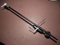
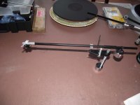
Hear is mine no grommets or O rings just the Thread it's a monofiliment not sure what it's strength is as it came from wife's sewing box.
Iv'e gone through various methods of attaching the C/w & IMHOP this is so far the best.
The arm is very stable now.
It grips the bear tube more than enough for azimuth to be adjusted, in fact the heavier the weight the more it grips. No sliding of the weight in any direction, & it's about as de-coupled as it can be.
Also the amount of damping to the arm, this method introduces is about as minimal as it can get.
I can't see a way of making it any simpler.
Though with a more elaborate connection of the thread to the weight, ie somehow wrapped around the weight it might be possible to stabilise the weight further, perhaps using two threads!!!!
Perhaps spacing the threads loops further apart might gain an advantageb.
I will play around with the olives till I get it just the way I want it.
But I think this part of the "219" has gone as far as it can, how can it get more simple & be as effective.
What do you think ?
Attachments
Roksan have a pdf on their website explaining the technology in their 'intelligent' tonearm. It actually gives enough information for a reasonably skilled machinist to replicate it ( the whole tonearm )
It's a good read for anyone interested in tonearm technology and quite refreshing to see a manufacturer explaining their design methodology rather than obfuscating it.
It's a good read for anyone interested in tonearm technology and quite refreshing to see a manufacturer explaining their design methodology rather than obfuscating it.
availability of kits...
guys,
I had put together only a few kits, some time ago.
At this point I am looking at doing a Kickstarter project to finance machinery so that the arms can be produced in batches. I have always wanted to create a small business (like I'm going to ever get rich doing this) commercializing the Nanook 219 tonearm. By going this route, I could build a batch of say 20 complete arms and have them ready to go. It would also make This is not unlike the "Terminator" tonearm, which is a version of the Poul Ladegaard DIY airbearing tonearm. There is some concern when working on the hardened aluminum arrow shafts concerning debris, and the care required to drill out any required holes. Any making these arms are highly urged to use appropriate eye protection..
I haven't decided on any rewards yet, but am thinking about offering complete arms as the top level one. Then perhaps proper blueprints, and a thorough construction guide. and perhaps the major components to allow one to make their own (arm tube, male bearing and installed female bearing , with blueprints and construction guide). I'm still thinking on this.
The issues in trying to do this are many. One thing is for sure: anybody purchasing a tonearm don't want it to look like it came from my kitchen table (which is nothing like Papa Pass'). Now of course, us DIY types can live with "fugly", but a buying public will not. You know what the biggest hassle is? Getting a tonearm lift! They are expensive, and not necessarily easy to make accurately. If I had the machinery I think I need, I could make something very basic, but properly functioning and cosmetically good looking.
This is not intended to stop any from making them, just to provide arms and sub-assemblies to those that don't have access to the limited machining capabilities (as in a drill, a Dremel, etc) that are required to make their own DIY version. I have suggested to some that I might start a blog for those interested in step by step construction instructions.
OK, now back to the c/w....
vdi_nenna: nicely done. It looks as though it should function as the Roksan version. It looks very good and follows my "use existing stuff" idiom as much as possible. Also the tonearm base has obviously been thought out., clearance for the counter-weight is not a problem with your implementation.
For all: The lighter the c/w, the farther from the pivot it needs to be and the less likely it will be interfered with by the tonearm base.
Jay and Chris: I've tried them all, and to me the best solution is still the heat-shrinked "stub end" and string or wire. The point of the heat shrink its to allow for some grip. I had not had good luck without it, so that's what I've used. MY attempt at the Roksan c/w was to see if it could be easily duplicated and if there was any other benefit. I feel that the benefit over the string hung c/w is minimal at the least and in most ways the string hung c/w , because it is so simple, has a huge benefit.
Stew,
The string C/w is as simple as it gets, no screws, rubber of any kind, & it does Grip once you decide where you want your weight to be, it will stay exactly their, as long as there is weight.....It will NOT move.
I have an idea for a simple head shell.
Im sure i saw sme type finger lifts on ebay for £1
Hi Folks
If you are looking for a simple and effective headshell, look at the pictures I have posted. This is aluminium tube, filed down to half-way, filled with with epoxy putty-totally inert. I then use a 'saddle' which is the same principle as used on the Morch-but more robust. Getting the offset angle right is easy. It also includes an integrated finger lift. Close up pictures to follow.
Chris
nice, but...
Chris:
Look at where the rotation of the cartridge occurs with regards to the stylus tip. This is a (to me) fatal flaw with every headshell other than my version of the Scheu design. The devil is in the details...
Everybody falls into the same trap, unfortunately. Resolving this is but a small step away...you're so close!
That's the end of the bad , except the use of a separate "stub end (or what appears to be a stub end). Everything else looks top notch. I'd be proud to own that arm.
Siddley...
...ya Mr. Feynman himself. Not because I am a greatphysicist, but I admire the fact that he was that and so much more. I wonder what he might have come up with for a tonearm if he had decided to make one. Perhaps not unlike the 219? At least the 219 is simple, and Feynman always sought the simplest answer first.
Thanks for the offer, if I was on the same continent as you perhaps...
"Look at where the rotation of the cartridge occurs with regards to the stylus tip." Stew (#492)
Hi ChrisG139,
I 'think' Stew means that the stylus tip should be in direct line with the centerline of a straight tonearm - thereby reducing rotation forces (?). I've been collecting parts for a Nanook-style tonearm in addition to a linear tracker like you've made. In that other thread several of us have asked to see addition photos/info of the adjustable mount that you designed for it. Hoping you can respond there.
From a travail of reading about unipivots it seems that there are three principles for 'perfection' with a straight tube unipivot:
1. Unipivot bearing inline with the cartridge stylus.
2. Cartridge stylus tip inline with centerline of tonearm.
3. Counterweight position such that the center of gravity of the system is slightly below the plane of the stylus tip/tonearm pivot.
At least that's how I've read the stuff online. The "219" can or does meet two of the three criteria. Given how well many have reported the 'above the plane' 219 pivot works, is there any potential benefit of creating a 'pillar' for the tonearm, with the bearing at the bottom of the pillar and inline with the stylus? I think the "oak tonearm" (by Cactus Cowboy?) used a pillar to bring the pivot to the plane of the stylus tip.
Thanks for any response. My Easton arrow awaits conversion.
John
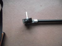
I must be having a 'thick' day!!
If the alignment means that the stylus must be on the centre line of the arm then it is already-please see enclosed picture. I know Stew's headshell is his favourite-I've made wooden ones before-I ended up with my design after a lot of trial and error-it combines sleek looks with rigidity and is totally inert-no ringing at all- (due to the epoxy filler) and makes adjustment a doddle. Perhaps this is why many well respected makers use variants of such a design?
Anyway-if there is something I'm missing I'm keen to be enlightened.
Regards
Chris
this is the intention...
Make a cartridge mounting plate. Drill 3 holes in it as indicated. It must be thick enough for the heads of the cartridge mounting bolts to be completely counter-sunk. Drill a single hole from the underside of the cartridge mounting plate that will allow a nut to be counter-sunk and then glued in place. Glue the nut in place. Screw the cartridge to the cartridge plate using the two 1/2" spaced holes
Make a simple dowel of metal or wood. Make a hole in it at pt B. Use an appropriate size and length bolt to push it from the top side of the "dowel", through the hole. The bolt will need to be + the thickness of the cartridge mounting plate. Screw the cartridge mounting plate to the dowel.
If seen from the side, the stylus point should be in alignment with the cartridge plate mounting screw, regardless of the rotation of the headshell. So the effective length will remain constant, regardless of the whichever alignment yhe end user decides upon.
This should also allow the adjustment of the stylus to the groove, reducing both stylus and LP wear. That's it
Attachments
Make a cartridge mounting plate. Drill 3 holes in it as indicated. It must be thick enough for the heads of the cartridge mounting bolts to be completely counter-sunk. Drill a single hole from the underside of the cartridge mounting plate that will allow a nut to be counter-sunk and then glued in place. Glue the nut in place. Screw the cartridge to the cartridge plate using the two 1/2" spaced holes
Make a simple dowel of metal or wood. Make a hole in it at pt B. Use an appropriate size and length bolt to push it from the top side of the "dowel", through the hole. The bolt will need to be + the thickness of the cartridge mounting plate. Screw the cartridge mounting plate to the dowel.
If seen from the side, the stylus point should be in alignment with the cartridge plate mounting screw, regardless of the rotation of the headshell. So the effective length will remain constant, regardless of the whichever alignment yhe end user decides upon.
This should also allow the adjustment of the stylus to the groove, reducing both stylus and LP wear. That's it
Is the distance from the tip of the stylus to the screw positions constant among all carts? If not, I am assuming this would be built for a specific cartridge? That could get risky, as there is possibility there are minute inaccuracies with the stylus tip and its alignment with the body, no?
My only experience is with Technics style headshell's thus far, so this is all just my mental thought, and nothing that I've tried.
- Status
- This old topic is closed. If you want to reopen this topic, contact a moderator using the "Report Post" button.
- Home
- Source & Line
- Analogue Source
- my latest iteration of "Nanook's 219 tonearm"..

