Here´s a link to some pictures of the unfinished amp:
http://hemsidor.torget.se/users/i/Iram/amp.html
http://hemsidor.torget.se/users/i/Iram/amp.html
Oh happy day...NOT!
Finished the PCB with the muting and bias circuitry late last night.
Did some tests on it this morning and after some minor changes I put it in place inside the amp, making the beast ready for a test run on the bench.
At first everything seemed fine, I had the expected 35VDC from the PSU (more or less unloaded). Then I started to increase the bias for the left channel up to about 2,7A and realized a need for fan cooling... Well, that was not a big surprise.
Tried to set the bias for the right channel to but that one didn´t want to, even though I turned the pot to maximum bias I didn´t get more than about 2A. (In the left channel I got 2,7A with the pot in about centre position...)
Strange, since the pots are in parallel an part of the very same voltage divider network...
There is also signs of oscillation, I can measure AC voltages here and there where there´s not supposed to be any AC. Very crude measurements though, done with a cheapest possible multimeter.
Don't sweat - it will be pretty hard to blow up.  I've dropped a screwdriver inside mine and had terrible accidents with meter probes and all that happens is the speaker makes some pretty rude noises then everything comes back to normal. not always the case with a class B amp though.
If it's oscillating the meter probably isn't reading right anyway. You do have a resistor on each fet gate don't you? *Right* at the gate lead. I initially used 10k, then took it down to whatever it is now. This will make it quite tame to enable you to do what is necessary to beat it into submission. Can you show a pic of the actual wiring around the fets?
I've dropped a screwdriver inside mine and had terrible accidents with meter probes and all that happens is the speaker makes some pretty rude noises then everything comes back to normal. not always the case with a class B amp though. If it's oscillating the meter probably isn't reading right anyway. You do have a resistor on each fet gate don't you? *Right* at the gate lead. I initially used 10k, then took it down to whatever it is now. This will make it quite tame to enable you to do what is necessary to beat it into submission. Can you show a pic of the actual wiring around the fets?
Yes, I do use a "Gate stopper" resistor on each of the mosfets.
(Ten in total, then)
220R, simply because that seems to be a common value.
Too low maybe?
With the bias turned to the minimum (about 0,5 A) the meter reads 4-5VAC on the gates and 1,6VAC on the top of the chokes.
Nothing gets past the output caps though...
The inputs are shorted to ground through small caps and the outputs are loaded with 6R8 power resistors in paralell with Zobel networks.
As I said before this was measured with a really lousy DMM, so I gave my recently purchased oscilloscope a try.
Without a decent probe, I must add. Made my own from a bit of shielded wire and some alligator clips.
The scope shoved straight lines with a some kind of blur around at the places where I measured AC vith the DMM.
I guess a better probe could be of great use here...
Maybe even a 10 MHz scope isn´t enough...
No pictures at the moment (have to get ready for a job interwiev in an hour...) but maybe I can fix that later. No webspace to put it on though...
Recursive posting, or, Mirrors facing each other.
You don't need web space. When you post a reply, just above the"submit reply" button there is a browse window and attach button for uploading a pic from your computer along with the posting. Use jpg's for pics, gif's for drawings and screenshots (gif's are sharper and way smaller for things that have large areas of constant colour).
Gif pic of attach button below. There is something recursive about attaching a pic of the attach pic button. Sort of like the acronym WINE, that stands for Wine Is Not an Emulator. http://www.winehq.org/
You don't need web space. When you post a reply, just above the"submit reply" button there is a browse window and attach button for uploading a pic from your computer along with the posting. Use jpg's for pics, gif's for drawings and screenshots (gif's are sharper and way smaller for things that have large areas of constant colour).
Gif pic of attach button below. There is something recursive about attaching a pic of the attach pic button.
Sort of like the acronym WINE, that stands for Wine Is Not an Emulator. http://www.winehq.org/Attachments


Now I´ve drawn a schematic using Windows Paint or whatever its called, but can I get it to show up here? Hell no.
I must be really stupid after all
Very well, after buying a BNC contact at the local audio/video store I made a slightly better probe for my scope and hooked it up to the amp once again. No signs of HF oscillation, so why the #¤%&/( does my DMM show several volts AC here and there?
If the DMM picks it up then the scope should too since they´re connected to the exact same points, right?
Another strange thing that I´ve noticed two times now:
When the right channel has been warmed up for a while at about 1,5 A bias it suddenly gets impossible to adjust the bias, it just stays the same no matter how I turn the pot. Something is more than a little wierd here, I think it´s time to check that bias circuit again.
At last something good: The choke filtering in the PSU seems to work very good, with both channels idling at 1,5A there was only 10 mVpp of sinewave shaped hum on the rails. On the first cap (before the choke) there was 1,5 Vpp sawtooth ripple, so the choke must be doing a great job there!
Attachments
Checked the bias circuit an hour ago, changed some resistor values and scraped with a knife between some of the PCB (Ok, veroboard) tracks that where suspicioulsy close to each other.
I don´t know what it was that did the trick but now it suddelny seems to work just fine! The bias can be adjusted from about 0,5A up to too much (!) on both channels equally.
Still can´t figure out why I´m reading AC signals on the multimeter though, when there´s no trace of them on the scope.
Very well, I biased both channels to 2 A and let it warm up for a while and DAMN, it´s hot!

Not that I didn´t know that class a amps get hot, I´ve built several before this one but this one is the biggest.
I´ll definitly will need fan cooling to reach 3 A idling current without smoke.
One good thing though is that the thermal coupling between Mosfets and heatsinks seems fine, I can´t feel much temperature difference between the metal parts on the mosfets and the heatsinks.
Tomorrow I´ll see if I can find something to measure the temp with, would be interesting to see how hot it really gets...
I don´t know what it was that did the trick but now it suddelny seems to work just fine! The bias can be adjusted from about 0,5A up to too much (!) on both channels equally.
Still can´t figure out why I´m reading AC signals on the multimeter though, when there´s no trace of them on the scope.
Very well, I biased both channels to 2 A and let it warm up for a while and DAMN, it´s hot!
Not that I didn´t know that class a amps get hot, I´ve built several before this one but this one is the biggest.
I´ll definitly will need fan cooling to reach 3 A idling current without smoke.
One good thing though is that the thermal coupling between Mosfets and heatsinks seems fine, I can´t feel much temperature difference between the metal parts on the mosfets and the heatsinks.
Tomorrow I´ll see if I can find something to measure the temp with, would be interesting to see how hot it really gets...
Attachments
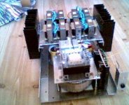
That's a cool looking choke farm you've got there, mister. You are running five paralleled IRFP540's per channel aren't you? That means only 500 - 600mA drain current each. OK for durability but it also means the fets are running right at the bottom end of their transfer curve, being a 28 amp fet and all.The bottom of the curve is where it is most curvy. Provided it will handle the dissipation, you will get better distorton figures if you run the entire current through a single fet. Won't look as cool though.
You are running five paralleled IRFP540's per channel aren't you? That means only 500 - 600mA drain current each. OK for durability but it also means the fets are running right at the bottom end of their transfer curve, being a 28 amp fet and all.The bottom of the curve is where it is most curvy. Provided it will handle the dissipation, you will get better distorton figures if you run the entire current through a single fet. Won't look as cool though.Well, I guess I could use one IRFP460 (280W 20A) per channel but that would mean a lot of work since I´d have to change heatsinks and so on. There´s already too many holes drilled in my heatsinks. Extra work and costs is not what I want right now
What I really need is a different power transformer, this one gives a bit too high voltage that does nothing but generates heat.
I´ll keep my eyes open for a fat 18-20VAC toroid, that would be more suitable than the 24VAC I´m using now.
Today is the big day for the first listening test if everything goes as planned.
 While listening to it you will probably spend a lot of time marvelling over how something so simple can sound so good, especially seeing it uses el-cheapo Hexfets and not some la-di-da audio mosfets. Keep us all up to date with any mods. Keep on rockin'.
Yeah, I know about simple amps, the only complex amp I´ve ever built was a solid state PP thingy that I ditched after a couple of weeks when the second set of output devices went up in flames. Still haven´t managed to burn a single transistor in a
SE amp, and I´ve built several in different flavours.
Hooked up the scope last night and did some measurements using a audio test CD as a tone generator.
At 1,6-1,7 A idle current per channel (which is max without forced cooling)I got 20Vpp into 7,5 ohms before clipping. 6,25W if my maths are correct.
A bit shy I thought, so I placed a 80 mm fan close to the right channel heatsink and cranked up the bias to the full 3A with the fan running at full speed.
That gave 27 W out and a really hot dummy load...
Still 9 W lower than the calculated 36 W, but I can live with that if necessary.
Square wave response is far from perfect, there was quite a bit of overshoot and ringing.
A real tone generator and some dummy loads that can handle the power longer than two seconds would make my life a lot easier at this moment.
Will have to to something about the too high rail voltage some time, lowering it to 26-27 volts instead of the 31,7 that is now would decrease the power dissipation by 15 W per channel.
Hopefully without lowering the output power noticably.
Since there seems bo be a lack of toroids at suitable values I´m thinking of removing some turns from the secondaries on the one I have.
Not an easy task I think, since it´s wound with copper bars rather that copper wire...
Well, what about the sound?
I´ve only listened a couple of ours, if even that, and the first impression is that this amps strength lies in the lower frequency region.
Grunty might be a good word to describe the bass response, and when I listened the bias was set to only 6 W output, At full power it will probably be even gruntier
The mids and highs doesn´t exactly have the sweetness of my 6B4G SE amp, but that was quite expectet as I guess DHT:s are hard to beat when it comes to sweetness.
I´m yet to try a different driver stage, the one used now is exactly similar to the one in the first prototype and that can be heard. As soon as I get the parts I´ll try RC-coupled triodewired PL83:s without cathode followers. Might sound better, might sound worse, who knows?
You could always get a small low voltage transformer and put it's secondary in series antiphase with the big toroid primary to lower it's input voltage. That way your toroid remains intact so you can still use it for another project later on if you want.Originally posted by Fuling Since there seems bo be a lack of toroids at suitable values I´m thinking of removing some turns from the secondaries on the one I have.
Not an easy task I think, since it´s wound with copper bars rather that copper wire...
Good idea, but too late
It wasn´t really that hard to wind of some turns, I did it this morning and it went just fine. Now the rails are down to 27,5 V at full load and the amp gets hot but maybe not too hot. I still will add some fans at least to get some ventilation inside it.
Measured the output power again minutes ago and at 3A bias I reached 30 W. Good enough I say!
Will run more tests tonight, including listening at full bias.
Now I have to go to work... things like that should be forbidden on Sunday afternoons...
Just when things started to move in the right direction towards finishing the amp dark clouds gathered above my head...
The current sharing between the mosfets is completely "fubar".
There is a huge temperature difference between the mosfets, it seems like only one per channel does the job and those are HOT while the rest just gets a little warm...
Well, i guess that´s what happens when using unmatched devices.
I guess the best cure is to change to one BIG mosfet per channel.
That means new heatsinks too, since the one I´m using now where already used and full of holes. If I drill even more holes there won´t be any aluminium left...
Did I just see a lot of money leaving my pocket to never return...?
Well, a 30 W class a amp is a quite serious project and I´m not abandoning it because of some stupid mistakes.
On each fet, tie each gate to drain and pull 100 mA through each and note the source to drain voltage. Most will probably be in the range of 3.4 to 3.6v Put the closest matched pair on one heatsink and the other closest matched pair on the other. You don't really need 5 per side.
- Status
- This old topic is closed. If you want to reopen this topic, contact a moderator using the "Report Post" button.
- Home
- Amplifiers
- Solid State
- My first ever Class A amp.