
Tranny School again.
Righto. I wound one winding for my choke and it was a disaster. Wound it over a rectangular piece of wood and it was just too tight to fit over the core! Had a second try this time much looser and using less turns - about 120. Strange thing though, I measure the inductance using a bridge and it was 47mH, yet when I applied AC to it in 10 volt steps from 0 to 100v and graphed the current and impedance (*most* instructive) it averaged at about 80mH at 6 amps before the impedance started to droop as saturation approached. I used a 0.25mm sheet of plastic for an airgap. Anyway, it would have been quite good enough for an amplifier but seeing the winding space was only about half filled the temptation was just too much...
I got busy and made a bobbin for it out of aluminium. BTW, if you have a choice, use a tranny that already has a bobbin; it will make life sooooo much easier. One thing I made sure of was that the ends of the bobbin were insulated from each otherwise being metallic it would have formed a shorted turn.
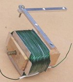
As you can see from the pic, I used a block of wood with a bolt passed through the centre and the threaded end attached to something solid. The block is rotated by the finely crafted mil-spec handle. Bunged on 234 turns of 1.25mm wire, I did.
Righto. I wound one winding for my choke and it was a disaster. Wound it over a rectangular piece of wood and it was just too tight to fit over the core! Had a second try this time much looser and using less turns - about 120. Strange thing though, I measure the inductance using a bridge and it was 47mH, yet when I applied AC to it in 10 volt steps from 0 to 100v and graphed the current and impedance (*most* instructive) it averaged at about 80mH at 6 amps before the impedance started to droop as saturation approached. I used a 0.25mm sheet of plastic for an airgap. Anyway, it would have been quite good enough for an amplifier but seeing the winding space was only about half filled the temptation was just too much...
I got busy and made a bobbin for it out of aluminium. BTW, if you have a choice, use a tranny that already has a bobbin; it will make life sooooo much easier. One thing I made sure of was that the ends of the bobbin were insulated from each otherwise being metallic it would have formed a shorted turn.
As you can see from the pic, I used a block of wood with a bolt passed through the centre and the threaded end attached to something solid. The block is rotated by the finely crafted mil-spec handle. Bunged on 234 turns of 1.25mm wire, I did.
Attachments
Ta-dahh!
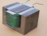
Now the I section goes on with the 0.25mm plastic sheet between it and the E's. you can just see it sticking out a bit. Then I ran 2 amps through it to hold the I's down tight while I taped it together with ordinary sticky-tape. Even with only 2 amps running through it the magnetic force is unbelievable; I couldn't slide the I piece across pressing as hard as I could with both my thumbs. There was probably in excess of 100kg attractive force! Amazing for 2 amps. Given this version has about double the turns of the previous one it should be good for about 320mH at 3 amps.
See? Now there is no excuse for not using chokes. You have a virtually unlimited supply of suitable transformers in old microwave ovens.
/Circlotron - wonders if the green enamelled wire will sound better than red.
Attachments
Still waiting for my double C-cores to arrive. They will probably show up at monday, at least I hope so.
In case they don´t show up at all (they come from a surplus store and there is a chance that they are out of stock), then I have a plan B:
Remove the existing windings from a pair of 150VA EI transformer kits that I bought for a whole different purpose some time ago, and then wind on as much 1,2 mm wire that the bobbin can take.
150 VA is quite a bit smaller than those microwave transformers of yours but it would probably work fine as an alternative solution.
By the way, how much inductance is needed to get a descent frequency (bass) response into 8 ohms load?
I read 600mH somewhere, but that seems a bit much I think.
The BIG inductors on my amp are about 80mH so that is about 15 ohms reactance at 30Hz. Seems to work just fine if you ask me. Did I mention that the DC current you need to run is rail_voltage / speaker_impedance? I have approx 28vdc rail so that would pull 3.5 amps through an 8 ohm resistive load; so 3.5 amps dc it is.
So with 32 volt rail and 8 ohm load the bias should be 4 A.
The power transformer can handle that, no problem, but the chokes will probably not since they´re airgapped for 3 A. Changing the gap is not an option since the choke is held together by a welded steel frame and the whole thing is dipped in epoxy.
Well, I guess 3 A bias is enough for quite a lot of pure class A power...
(of course I could calculate the expected output power but for the moment I´m suffering from an horrible hangover which gives me the feeling that my brain has been replaced by a jackhammer )
)
The power transformer can handle that, no problem, but the chokes will probably not since they´re airgapped for 3 A. Changing the gap is not an option since the choke is held together by a welded steel frame and the whole thing is dipped in epoxy.
Well, I guess 3 A bias is enough for quite a lot of pure class A power...
(of course I could calculate the expected output power but for the moment I´m suffering from an horrible hangover which gives me the feeling that my brain has been replaced by a jackhammer
)Disaster!!!!
I got the chokes today and guess what: I got the last SEVEN ones he had!!! That makes nine with the two I already had.
Four per channel should be enough I think, but that only leaves one for the PSU and thats bad news!
I need two for the PSU since one choke alone can´t handle the current drawn by two channels.
Bye bye sweet CLC filter and hello nasty BJT series regulator...
I guess three chokes (75mH) for each channel is a bit too small to get enough LF response.
This requires some serious dri...thinking
Serious dribbling? Well, whatever it takes...Fuling said:I guess three chokes (75mH) for each channel is a bit too small to get enough LF response.
This requires some serious dri...thinking
Nah, 75 mH will go ok, just you wait and see.
Or of course you can just keep your eyes peeled for old microwaves.
Well, serious drinking...
So, if 75 mH is enough, that means that all my problems concerning the chokes are solved!
I feared for a while that I would have to wind my own PSU chokes, something that only could have ended in disaster and a lot of swearing. (I remember the language I used about a year ago when I tried to wind a pair of interleaved output trannies... not pretty)
Now I will concentrate on finding capacitors and heatsinks for a reasonable price. I have already ordered three 15000µF/40V
Rifa caps from some guy who had them for sale but much, MUCH more will be needed to get a quiet power supply.
I´ve tried CLC filtering for SS class a amps before and failed because of using way too small chokes and caps. This time it´s for real, though
Heatsinks: I´m thinking some kind of tunnel shaped thingy with a fan or two in one end, run at lower speed. All the mosfets will together dissipate about 160-180 watts, that means HEAT in my experience.
This will be something quite different from those 2-3 watt tube amps I´ve been messing with the last year(s)
3 Amps bias, that should be enough for about 35 watts I think.
Sweet.
Wish me luck
Hi Fuling,
I am following this with great interest. I too wonder how much power you'll get from this novel design.
Fuling, huh? Did you know of Jim Fuelling, who died in Southern CA last December and pioneered a lot of very impressive auto engine designs, like a 1200 bhp QUAD4 as an experiment for GM, and a W3 triple Harley Davidson of 2.5 litres?
How will you control the stage current?
Hugh
Hi
Never heard of Jim Fuelling but if he designed 2,5 litres engines for HD then I´m sure he was a decent guy
My nickname "Fuling" means something like "ugly guy" in swedish, if you all wanna know I could also tell you all what Brad Pitts last name means in swedish, but I think I´ll let that one be...hehehe
I did a little calculator excercise late last night, and that´s how I came up with the number 35 watts.
Current control, yes... I think I´ll use just a decoupled resistive voltage divider (adjustable, of course) connected to the gates of the mosfets via a 100k resistor. Those chokes connected between source(s) and ground will have a DCR=1,2-1,6 ohms, high enough to keep the current nice and stable I think.
Cheers/
Daniel
Never heard of Jim Fuelling but if he designed 2,5 litres engines for HD then I´m sure he was a decent guy
My nickname "Fuling" means something like "ugly guy" in swedish, if you all wanna know
I could also tell you all what Brad Pitts last name means in swedish, but I think I´ll let that one be...heheheI did a little calculator excercise late last night, and that´s how I came up with the number 35 watts.
Current control, yes... I think I´ll use just a decoupled resistive voltage divider (adjustable, of course) connected to the gates of the mosfets via a 100k resistor. Those chokes connected between source(s) and ground will have a DCR=1,2-1,6 ohms, high enough to keep the current nice and stable I think.
Cheers/
Daniel
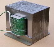
Chokes are easy-peasy compared with an output tranny. Look. Tonight I rewound another one of my microwave oven trannies, this time the one with a bobbin and wow! it was *HEAPS* easier. It should be good for about 350 mH or so at 3 amps. Just a matter of fiddling the turns and/or the gap. The whole thing from go to whoa was about 1-1/4 hours work. Once you haver done it once you will never look back. Just make sure you use one with a bobbin. You can see in the picture I left on the 240v winding because this has 1mm wire and about 250 turns. Would have been ok all by itself actually. This winding measured 1 ohm. I added the green winding with 1.25 mm wire. Both windings in series should come to about 1.4 Henries!Fuling said:I feared for a while that I would have to wind my own PSU chokes, something that only could have ended in disaster and a lot of swearing. (I remember the language I used about a year ago when I tried to wind a pair of interleaved output trannies... not pretty)
A real father doesn't back away from the most fearful dirty nappy/diaper. A real diy'er is not scared of winding his own magnetics. Heck, it's way easier than building a whole amplifier. Just try it, you'll be amazed. But I repeat once again: use a tranny that has a bobbin.
Attachments
Is this a case of nominative determinism ?.Jim Fuelling, ....... pioneered a lot of very impressive auto engine designs......
Eric.
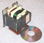
That one looks really professional, Circlotron!
I feel that I have to tell you guys about a little trip I did today.
Me and a friend took his car and went out to visit some junkyards and fleamarkets to see if we could find anything useful.
This is what I brought home:
One big heavy Sansui integrated amp.
One PSU from an old electric organ.
One old and reeeeaally good looking tube radio in nice condition.
Seven big motor run capacitors.
Six power transformers from 30 to 150VA. The biggest one with black endbells.
All this for 350 SEK (about 35-40 USD)
Feels like I will spend the rest of this day diggin´through some serious junk. I´ll be back
Your thoughts on how diff. re-wound trafos will sound in a multi-channel amplifier?
Circlotron,
I've been following this thread with some interest. Now that you have two very different rewound microwave oven transformers, what are your thoughts on how different they might sound when in a multi-channel amplifier?
I have a home theater and will be building a 5 channel amplifier for the surround sound. I'm tossed between building a set of class "A" amplifiers, or a set of "gainclone" type amplifiers. (clearly, they would be much faster to build)
Idealy, I would like something in the 50 to 100 watt range, but I am currently using a class "D" 15 watt per channel amplifier salvaged from a pair of Philips "computer speakers" and it is plenty loud for most movies. For that reason, the "gainclone" at 35 watts would probably be fine.
I'm not afraid of the massive heatsinks and power supply needed for your class "A" amplifier design. I would build it as a set of 5 chassis. (perhaps a sixth would hold the power supplies)
I'm sure I could locate five old microwave oven transformers, but the odds of them being identical in size or construction is somewhere between slim and none.
I know I can use an inductance bridge to try to get them close to the same inductance when re-wound, but will their different physical sizes and construction make a difference in the way they sound in your amplifier circuit?
Your thoughts?
Joe L.
Hi J.L.
As regards different types of microwave transformers, I haven't actually seen enough of them to be certain, but I would not be surprised if there were only a few different types made by only a small handfull of manufacturers. If you don't have an identical pair, try and pick two that are the same size, have the same lamination thickness and most of all, that they have a bobbin. Repeat after me - "bobbin".
As for difference in sound, well it's a bit hard to say but if they have pretty much the same inductance and the core looks the same they would probably be pretty close. If they were going to differ I would think it would be in the negative going half cycle where it is only the stored energy that drives the speaker and mosfet source controls how low it goes at any given moment. On positive half cycles the mosfet source says "do this" and the choke voltage therefore the speaker voltage just does. If the choke is running out of flux and therefore current on the negative swing then there will be a difference but with the size chokes and power levels and frequencies we are talking about that is virtually impossible.
Probably the only way the two chokes would sound different to each other is if you actually *knew* they were not physically identical. If they were unseen inside a closed box and you never knew they were different then I doubt I could hear the diffeence at least.
Circlotron,
You are probably right in that there are a limited number of manufacturers of the transformers in microwave ovens, but I'll bet their core sizes vary all over the place. It will just make the task of finding a matched set more interesting.
I guess I'll have to start looking for trashed microwave ovens.
(repeating after you) ...bobbins... ...bobbins... ...bobbins... ...bobbins...
Joe L.
Bobbins bobbins bobbins bobbins...
...could be made out of PCB laminate (with the copper removed)
and epoxy glue, I think. That´s the best idea I could come up with a while ago when I had plans for making some six-chamber bobbins for a set of plate chokes.
I haven´t tried it, but I think it should work fine.
Airgaps: There must be a scientific way to calculate the required airgap for this kind of chokes, right?
I can imagine some kind of formula involving the number of turns, core area and maximum DC or something like that. Anyone who knows??
Also, there must be a way to determine the minimum inductance needed to get the desired frequency response. A ratio between choke reactance and load impedance at 20 Hz or something like that. Please share with me if anyone knows this!
- Status
- This old topic is closed. If you want to reopen this topic, contact a moderator using the "Report Post" button.
- Home
- Amplifiers
- Solid State
- My first ever Class A amp.