I thought something like that too for a while, but as I still had to order other parts to get finished I also ordered new BIG mosfets.
IRFP260N, 300W in TO247 case. They weren´t really that expensive and after a thorough look at the heatsinks I found that they can be used with the new mosfets without drilling any more holes. Lucky me!
The parts should arrive at Friday so until then I´ll disassemble
the output stage/heatsink sections and prepare for the mkII version.
Banned
Joined 2002
Well here is a picture of my layout for my aleph 2's im ordering my aluminum in a few days to start and finnish the chassis. Then to start Populating the Front end boards and the Fet boards then i should be done. So far i have spent lots of cash on these. They better sound good. : O ) 
Banned
Joined 2002
Banned
Joined 2002

I´m happy to say that it worked exellent!!
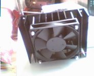
I put the pieces together enough for a heat test and with both channels at full bias the temperature measured directly on the Mosfets reached 56 degrees Celsius!!
That was measured with the fans operating at 4V instead of 12 to get the noise down.
With fans turned of the temp. went far above 60 degrees within minutes.
Finally it seems that I can continue finishing the metalwork without being interrupted by any stupid mistakes in the circuitry")
I put the pieces together enough for a heat test and with both channels at full bias the temperature measured directly on the Mosfets reached 56 degrees Celsius!!
That was measured with the fans operating at 4V instead of 12 to get the noise down.
With fans turned of the temp. went far above 60 degrees within minutes.
Finally it seems that I can continue finishing the metalwork without being interrupted by any stupid mistakes in the circuitry
Keep removing parts till it stops, then go back one ;-)
A partial schematic of my amp is back on this post here. http://www.diyaudio.com/forums/showthread.php?postid=68530#post68530 A full downloadable one is a few posts further down. Anyway, it has being going problem-free for 5-1/2 months now and I am really quite pleased with it. But 5-1/2 months is a long time in diy, and I have been thinking how would I have designed the amp knowing what I know now? After reading and thinking =lots= about negative feedback, opamps and lotsa other stuff, I decided to bite the bullet this weekend and go back to basic principles and make it a simple amp, the way I really wanted to first time around, before I got carried away.
Soooo..., First thing to get the chop was global nfb. A few experiments lately led me to think I can get by quite nicely without it in this particular amp.
Also removed bootstrapping cap for 1st stage fet supply rail. Actually I just ran the negative end of the cap to ground so it is still some use.
Removed ccs from drain lead of 1st stage and replaced it with a 1k resistor. Also put 100R unbypassed resistor in source lead to give local nfb and set the stage gain to x10. It will still swing about 90v p/p before distortion gets visible but I only need about 55v p/p for full output.
Ditched local feedback R&C from drain to gate of 1st stage. Fiddled value of bias resistors because of 5.9 volts drop across source resistor.
Increased gate resistor from100R to 1k. This fet (ST P3NB60) has a relatively small junction and is really fast and I didn't feel 100R was quite enough to be doing a good job keeping it totally stable.
Dumped opamp input stage buffer. I can hear the cheering from here! Seeing I didn't have the signal going through a 3k3 feeding a virtual earth at the fet gate anymore I simply didn't need it. The best opamp is no opamp.
So then how does it sound? I have only listened to it for about an hour and not on a wide variety of stuff. Noise-wise, with the inputs shorted, if you put your ear about 2cm away from the tweeter dome you can just just just hear a little hiss. From the woofer there ain't nuthin. Sound-wise, there is foreground music and background music. Before, the foreground stuff seemed to dominate the stage and put maybe a filmy haze in front of the background stuff. Now that is gone I think. I find myself concious of little things like the slight buzz of a bass guitar string on the fret as the finger is lifted, minor background noises, and the vocals seem a little more natural. AKSA, that track with the girl telling the story of Charlie's homing pigeon, the voice is like *there*. You can readily hear the saliva squelch in her mouth as she opens it. Well, you can!
Crank up the volume a bit and transient stuff like snare drums seem to be a little better defined. There used to be a little LF instability before, making the woofer cones slowly move in and out a bit at high volume, this is gone now. Sound stage is pretty much the same as before, pretty good. There wasn't and still isn't any 3D depth to the sound like some people talk about though. Maybe it's just my room?
I will re-draw the schematic to show the changes. It is now dead simple as you will see, and sounds great. All in all, quite a worthwile mod. The specs would probably measure worse but it sounds better. For a simple low-buck amp, I say give it a go. It is extremely nifty.
P.S. the cct is practically identical to that in the very start of this thread. Just no global nfb, bottom of the bootstrapping electro now goes to ground, and no cap partway down gate bias voltage divider on first stage. Darn I could have saved myself a lot of trouble (and learning).
A partial schematic of my amp is back on this post here. http://www.diyaudio.com/forums/showthread.php?postid=68530#post68530 A full downloadable one is a few posts further down. Anyway, it has being going problem-free for 5-1/2 months now and I am really quite pleased with it. But 5-1/2 months is a long time in diy, and I have been thinking how would I have designed the amp knowing what I know now? After reading and thinking =lots= about negative feedback, opamps and lotsa other stuff, I decided to bite the bullet this weekend and go back to basic principles and make it a simple amp, the way I really wanted to first time around, before I got carried away.
Soooo..., First thing to get the chop was global nfb. A few experiments lately led me to think I can get by quite nicely without it in this particular amp.
Also removed bootstrapping cap for 1st stage fet supply rail. Actually I just ran the negative end of the cap to ground so it is still some use.
Removed ccs from drain lead of 1st stage and replaced it with a 1k resistor. Also put 100R unbypassed resistor in source lead to give local nfb and set the stage gain to x10. It will still swing about 90v p/p before distortion gets visible but I only need about 55v p/p for full output.
Ditched local feedback R&C from drain to gate of 1st stage. Fiddled value of bias resistors because of 5.9 volts drop across source resistor.
Increased gate resistor from100R to 1k. This fet (ST P3NB60) has a relatively small junction and is really fast and I didn't feel 100R was quite enough to be doing a good job keeping it totally stable.
Dumped opamp input stage buffer. I can hear the cheering from here!
Seeing I didn't have the signal going through a 3k3 feeding a virtual earth at the fet gate anymore I simply didn't need it. The best opamp is no opamp. So then how does it sound? I have only listened to it for about an hour and not on a wide variety of stuff. Noise-wise, with the inputs shorted, if you put your ear about 2cm away from the tweeter dome you can just just just hear a little hiss. From the woofer there ain't nuthin. Sound-wise, there is foreground music and background music. Before, the foreground stuff seemed to dominate the stage and put maybe a filmy haze in front of the background stuff. Now that is gone I think. I find myself concious of little things like the slight buzz of a bass guitar string on the fret as the finger is lifted, minor background noises, and the vocals seem a little more natural. AKSA, that track with the girl telling the story of Charlie's homing pigeon, the voice is like *there*. You can readily hear the saliva squelch in her mouth as she opens it.
Well, you can! Crank up the volume a bit and transient stuff like snare drums seem to be a little better defined. There used to be a little LF instability before, making the woofer cones slowly move in and out a bit at high volume, this is gone now. Sound stage is pretty much the same as before, pretty good. There wasn't and still isn't any 3D depth to the sound like some people talk about though. Maybe it's just my room?
I will re-draw the schematic to show the changes. It is now dead simple as you will see, and sounds great. All in all, quite a worthwile mod. The specs would probably measure worse but it sounds better. For a simple low-buck amp, I say give it a go. It is extremely nifty.
P.S. the cct is practically identical to that in the very start of this thread.
Just no global nfb, bottom of the bootstrapping electro now goes to ground, and no cap partway down gate bias voltage divider on first stage. Darn I could have saved myself a lot of trouble (and learning).Putting it in numbers.
Righto then. I decided to do some measurements on the input stage of the amp just to see what it was like. I threw one together on the bench and dialed it up to 60v p/p output for about 6v p/p input. Also there was no low pass filter on the input that the complete amp has.
Frequency response is -3dB at 1.8 Mhz. This is running open cct i.e. no load; any load capacitance would reduce this a bit. Also, this was with the 1k gate resistor; making that a lower value would make the response go out even further.
Slew rate at 1.8 Mhz 42v p/p (-3dB) is 475 v/uS at the sinewave crossover point so that ok.
Square wave rise time = 198 nS @ 60v p/p
Fall time = 212 nS @ 60v p/p
Output noise with input shorted is about 0.6mV RMS. I measured this across the load resistor, not from drain to ground because if you take the signal from drain to +V the constant current effect of the mosfet rejects any power supply ripple.
Attached is the complete amp cct less the power supply.
It totally rocks - it's the nicest sounding amp I've ever had!
Attachments
Banned
Joined 2002
I'm in good company then! The fans are actually running off about 5.5 volts. I have an adjustable regulator feeding them. Just not on the schematic, that's all. As a matter of fact, the majority of the noise is not from the fan blades at all now, but from the vibration caused by the square wave drive of the fan motor windings. It makes a brrrrrr noise at about 70 Hz or so. I once opened up one of those fans and looked at the voltage waveshape generated by the coils when the fan was spun by hand. It was more or less trapezoidal - square wave but with a very sloping straight line transition from pos to neg. I reckon if I could make an external driver to run it with *that* waveform instead of the normal square one it should be a lot quieter. Someday...JasonL said:i would personaly make the fan run at a slow rpm that way the noise is low and it keeps it cool.
First I have to admit that my 30W class A project has been put on ice for a while. Someday when I have the time, money and inspiration I will use the parts to build a pair of monoblocks using the same topology.
Anyway, I´ve been doing some thinking about this choke loaded mosfet thing and I came up with an idea.
What if we used two source followers loaded by a choke with a grounded center tap?? That would cancel the DC flux in the choke
(= allows us to use a much smaller core without airgap) and the need for output coupling caps is eliminated.
BUT!! Would that be a push-pull amp och would it qualify as a balanced SE amp??
My guess is that it would be a PP, since it would work in class B or AB. But lets say that we bias it in class A, would there be any difference from using two separate, airgapped chokes??
Since I have overcome my phobia of winding inductors, this might be something to put in my list for upcoming projects...
Fuling said:Anyway, I´ve been doing some thinking about this choke loaded mosfet thing and I came up with an idea.
What if we used two source followers loaded by a choke with a grounded center tap?? That would cancel the DC flux in the choke
(= allows us to use a much smaller core without airgap) and the need for output coupling caps is eliminated.
Put a second winding on the choke as well, the ends going to the drains and the centre tap to V+. Then put a large capacitor (filter cap size) from left drain to right source, and another cap from right drain to left source. Connect the speaker to the sources. Bias it up in class A and it sounds quite nice. The choke core does not have to be fancy iron - power transformer stuff works very well. I'll try and find the link to the one I made some time ago...
Circlotron said:I'll try and find the link to the one I made some time ago...
Ta-dahh! http://www.diyaudio.com/forums/showthread.php?s=&threadid=10658
Scare yourself and just do it! It's easy!! It works really well too!! If you don't understand it at first, that will not stop it working. It doesn't know that you don't know. What's more, even harmonic distortion caused by the square-law characteristic of gate voltage to drain current is cancelled. Also, there is no switch-on thump. And...... because it uses only N-channel fets, power output is scalable to truly ridiculous levels.Fuling said:I guess I´m stupid, but I can´t seem to understand how that thing works?!? *snip* I´ve got some research to do I think...
 buahahahaha
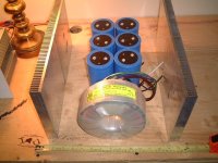
A couple of months ago me and my brother ripped apart an old wire EDM machine at his work and salvaged some 70-80 kg´s of junk, including some huge transformers and heatsinks.
The heatsinks are now morphing into a pair of Aleph 5 monoblocks (which is another story),
but what´s interresting for this thread is two of the transformers.
They came from some kind of threephase PSU, each one rated to >1kVA with a 230:105 voltage ratio. (Odd voltage and quite useless too). They weight in at 16kg a piece.
The windings are made of really thick wire, >2mm primary and >3mm secondary. Between the windings there are magnetic shunts but I guess they can be removed.
Since I can´t find any proper use for these monsters (except maybe wiring them back to back and use as an isolation transformer) I´m thinking about converting them into airgapped chokes.
The windings are already in place, so all I´d have to to would be to cut airgaps in the cores.
If I ever gather the guts to do this it could result in a very, VERY mean amplifier!!!
- Status
- This old topic is closed. If you want to reopen this topic, contact a moderator using the "Report Post" button.
- Home
- Amplifiers
- Solid State
- My first ever Class A amp.