Hello
wahab do you think these amplifier with lateral mosfet can achieve close or similar performance to the orig darlington?
I mean the circuit you posted last time.
I modded the layout from the darlington to the lateral mosfet in case someone interested.
Now nobody can say " I do not like the darlington devices"! I'm not interested on darlington, etc......
Here is the opportunity to try out the same topology with laterals.
I used the the color coded method since I draw the layout with the paint program with out any software.
So I do not have silkscreen, please do not ask. But these is so simple hard to imagine someone would have problem to find the component locations.
Of course I'm more than willing to help. The layout not tested yet but very likely is OK.
Greetings Gabor
Attachments
Last edited:
Hi Gabor ,
Since the schematic is the same as with Darlingtons , set apart
the components values , performances are close , with a slight
hedge in favour of laterals as their higher input impedance allow
lighter VAS loading and consequently more open loop gain that
will translate in lower distorsion although good quality darlingtons
would be on par.
Hi Wahab,
Thank you for the Lateral version of the circuit, I have nothing against darlingtons, infact I may build one with darlingtons and another with Lateral FETs. I have a ready made PCB that almost suits the driver stage and the later MoSFET output stage need minor modifications for the input circuit. Thats why I would like to build a Lateral version.
Thanks,
Hello
Here is the layout again with some small mode and I include the color codes.
I'll go over once more to make sure there is no error and after I'll post the black layout.
Al do these amplifier probably will not perform (who knows) as good as the "Hitachi mosfet amp" but these much simple and easier to build.
In case if these will perform same or close to the orig darlington I guarantee you will be happy with the result.
I do have some extra FET so probably I'll test it, and compare with the Darlington!
Greetings Gabor
Attachments
 & give a big thank you to wahab for the circuit!
For power transistors we have not to many option here .
We tried Motorola MJ11015/16 Darlington but get worst . There is not to many Darlington on the market . Very few amp was built from Darlington transistors .I know Hiraga Class A etc used the Darlington circuit but not the transistor it self . And we tried to use TIP142 /147 but BDW83C under the name of Morocco , or Texas Ins. was the best .
Philips had some good Darlingtons but today discontinued parts very hard to find and even they ask $30 for a piece .
Try Sanken? They have a few good darlington power transistors.
.......
I m surprised that some people hear difference in basses from an
amp to another one ........
Hi Wahab,
There is a lot about audio that doesn't appear 'possible' sometimes!
")
I compared the Bryston 4B with a Creek 5350 , a Rotel 970BX and a few others. The Bryston seemed to go an octave lower than the rest. Some very deep bass was audible on the Bryston but missing from the others and it was not due to frequency response. I've read about this performance of the Bryston and didn't believe it till I heard it myself. I've never seen anyone explain this , though it's ability to "go deeper" has been mentioned by many people on the Net.
Coming to the amp Gaborbella brought up on this thread.
Can you simulate the output stage as a CFP with low wattage Latfet like the 2SK216/ 2SJ72 with BJT bipolars like the 2SC5200/2SA1943 . If you have no Spice models then use the 2SK1058/2SJ162 . I don't have the Spice models of these Latfets. Output BJT run under normal bias ( maybe 50 mA ?) and also alternatively biased to turn on only after the driver delivers about 0.25 Amps or so ( depending on which Latfet you use).
Hi Wahab,
There is a lot about audio that doesn't appear 'possible' sometimes!
I compared the Bryston 4B with a Creek 5350 , a Rotel 970BX and a few others. The Bryston seemed to go an octave lower than the rest. Some very deep bass was audible on the Bryston but missing from the others and it was not due to frequency response. I've read about this performance of the Bryston and didn't believe it till I heard it myself. I've never seen anyone explain this , though it's ability to "go deeper" has been mentioned by many people on the Net.
.
Of course you can hear it, I'm one of the guy (out so many) who experienced that.
That why I try to pick (match) the components when I build a amplifier to get the best performance.
To me DIY almost would be senseless after one or two build if we could not hear the difference like how you wrote also, or we could hear just some min. differences.
Your Bryston is using lateral mosfet at the power stage if I'm right??
I post one more time the layout, I made some minimal appearance mode but, these can use foil caps at the power connection +/-...
I do not always use foil caps next to every electrolytics, usually I test them and after decide.
Greetings Gabor
Attachments
Last edited:
Hi Wahab,
Some very deep bass was audible on the Bryston but missing from the others and it was not due to frequency response. I've read about this performance of the Bryston and didn't believe it till I heard it myself. I've never seen anyone explain this , though it's ability to "go deeper" has been mentioned by many people on the Net.
Hi Ashok ,
Poor output current capability can be the culprit but then the Rotel
has a collection of output parraleled devices and unless they are limited
by a protection circuitry they should provide the necessary low output
impedance in large signal mode condition to get the basses smothness.
In another thread Jcx seems to point high output current requirement
as a design guideline.
for more fun you need the calcs for realistic loads
loudspeakers aren't pure resistors, even "polite" multiway often have |Zmin|< Rnominal/2
then you can adjust power dissipation for phase angle
add reserve for "pumping" resonace, sudenly reversing phase - the current peak can be >5x the Rnominal calc
Coming to the amp Gaborbella brought up on this thread.
Can you simulate the output stage as a CFP with low wattage Latfet like the 2SK216/ 2SJ72 with BJT bipolars like the 2SC5200/2SA1943 . If you have no Spice models then use the 2SK1058/2SJ162 . I don't have the Spice models of these Latfets. Output BJT run under normal bias ( maybe 50 mA ?) and also alternatively biased to turn on only after the driver delivers about 0.25 Amps or so ( depending on which Latfet you use).
If i understand correctly , implementing FET/BJT current feedback pairs
as power output devices.?..
No problem , i ll take a look at it but at first thoughts , the difference
will be mainly in output impedance , distorsions ratios should be close ,
i ll check the "exact" numbers.
Attachments
Hello
Wahab I would like to have a few question to you.
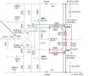
First I see you left out the 330pF capacitor from the modified darlington and the lateral Fet circuit to.
I think that was purposely. Can you gave me some hint, I do not miss that capacitor just I want to know is not an error.
Do you think these topology would work with out major mode with power BJT like the mentioned Toshiba 2SC2500 and complementary?
Please let me know before I etch the PC board, I'll give a try to the lateral version just to compare with the Darlington.
I see these topology getting more and more popular on the forum.
Also I got a lot of resistance from DIY-ers because the Darlington devices (what I like(because I heard in the amp).
I wish we could invent the newer Sanken darlington with the thermal track but not much valuable information on the NET about them.
Tomorrow I start to work on the Hitachi PC board, protect fro oxidation, drill the holes etc.
Some of my fund are hold by pay pal, I do not want to spend more from my pocket.. I already spent ## ### over the years on DIY parts.. These include DIY speakers, cables etc.
I want to order the resisters and the needed transistor.
Greetings Gabor
Wahab I would like to have a few question to you.
First I see you left out the 330pF capacitor from the modified darlington and the lateral Fet circuit to.
I think that was purposely. Can you gave me some hint, I do not miss that capacitor just I want to know is not an error.
Do you think these topology would work with out major mode with power BJT like the mentioned Toshiba 2SC2500 and complementary?
Please let me know before I etch the PC board, I'll give a try to the lateral version just to compare with the Darlington.
I see these topology getting more and more popular on the forum.
Also I got a lot of resistance from DIY-ers because the Darlington devices (what I like(because I heard in the amp).
I wish we could invent the newer Sanken darlington with the thermal track but not much valuable information on the NET about them.
Tomorrow I start to work on the Hitachi PC board, protect fro oxidation, drill the holes etc.
Some of my fund are hold by pay pal, I do not want to spend more from my pocket.. I already spent ## ### over the years on DIY parts.. These include DIY speakers, cables etc.
I want to order the resisters and the needed transistor.
Greetings Gabor
Attachments
Hi Gabor ,
Well , this capacitor (along with the 2.2K resistor) will reduce the high
frequency -3dB cut off to 130Khz , down from the 240Khz if it wasnt there.
I suspect that it was added as RF filter rather as well as slew rate limitation ,
as in Europe the radio broadcasting AM band start at 150Khz or so with
emitters less powerfull than in the 70s , but still being a problem for
whom is living not too far from the antennas , so if you have nearby
RF transmitters it can be usefull to implement the said capacitor.
Other than RF concerns , this also limit the signal slew rate to cope
with the BDW83/84 6us slow turn off.(2us or less for the BDW93/94)
Replacing the darlingtons with two drivers and two 2SA1943/2SC5200 pairs
wont improve the perfs by a sizeable amount providing the comparative monolithic
darlingtons are not beta starved , in wich case there will be
a difference when driving lower impedance loads than 8R , and this likely
is the area where Sankens could have an hedge over the STMicro BDWs ,
wich are requiring tests before mounting to eliminate low beta samples.
As for popularity of darlingtons , or rather lacks of , i think that it has
more to do with urban legend than real technical ground , seems that
experiences with decades old slow devices like TIPs or Motorola s early
production where kept as definitive conclusions for all possible monolithic
darlingtons , past , present and future ones....
May be the old slow darlingtons were not designed for audio so that they made a bad sounding amps. But iff they are made specially for audio then imagine: if IC, with hundreds of components, can be made "better" than discrete, why not darlington with only 2 parts? The only limitation is thus how the driver's emitter tied up at the output along with output emitter.
Does the latter fact limit the possible performance of the darlington? Technically, may be not. But I have never heard such output topology that sound good enough. (I prefer to modify my vintage amps output stage, with the cost of increased THD)
And I have those fast darlingtons specially designed for audio. And I have made a circuit that perform incredibly well in simulation (P3A input stage, but with different models). But the sound was just another darlington sound.
Anyway, I'm looking forward to any good designer to design a good sounding darlington amp to make me understand more about it. Until then, I'll stick with my urban legend opinion
Hello
Thank you wahab
I did added back that capacitor at least to the darlington (not to the lat FET version) in case if needed good to have the room on the PC boars so I can mounted it properly.
The guy who mode the circuit (at least he told me he designed it) he advised to use Texas Isnt. BDW
Unfortunately on that time it became obsolete so the best ever replacement ST Micro.
From Philips also 20 years a go had some BDX darlington in TO3 case (I think those were more popular in audio) but became obsolete also.
Thank God I found some ST BDW83C/84C (I think is orig because those were produced for order bent and shorter leads)..
May be I will order more after I test them if the seller still has them.
To me TIP was OK replacement but probably how you wrote the BDW types are better..
From other corp not worth to buy not even for half a price, probably only the Sanken SAP15P & complementary..
http://www.farnell.com/datasheets/3147.pdf
These are popular darlinton even in audio but to redesign these amp does not worth that much all!!!!
There is a German made MBL high end amplifier (not cheap at all) that still use the BDX type darlington (probably Philips produce to them in a large quantity) but in the market no longer available.. May be the lat FET will sound as good as the darlington and the problem will be resolved once in for all!
All do people say mosfet has softer bass than BJT, I will test it. I have mostly mosfet amp design from Mr. PASS and the Hitachi Lat mosfet amp(s) If is true the mosfet tend to have soft bass good to have at least a good sounding BJT (with good bass)
I did like the sound of the darlington very much!
Thank you one more time
Greetings Gabor
Any progress on the amp ?
I've just drawn up a schematic using Jap transistors and TIP142/147 based on your last schematic but with slightly modified parts values. Supply will be off board. Will attempt to make the board as small as possible.
Hope to have it ready in a few days.....if the work doesn't get stalled by unforeseen circumstances !
If it works Ok I might replace the 142/147 with 2SK1058/J162 and see what happens.
Cheers.
Wouldn't it be better to use these Darlingtons (see bottom of the page) than the old industrial craptanium from Texas, Philips or Motorola?
SANKEN ELECTRIC : Power Transistors : For Power Amplifier
You're right, Wahab. There will sure be an audible difference in that comparison.
SANKEN ELECTRIC : Power Transistors : For Power Amplifier
You're right, Wahab. There will sure be an audible difference in that comparison.
Hello
My advise to you please use first those transistors I used at my last test!
That will give you a base to compare some other Darlingtom, Lat fet etc...
Reason I write these because that was tested and works properly.
Al do Sanken produce some nice device not much information about and the chip inside built up not the same as BDW83C/ 84C or TIPs.
My last test I made with the TIP147/142- the result was incredible.
Yes I compared the TIP with BDW93C/94C and no audible difference at all! The TIP142/147 more rugged than the BDW93C/94C..
I know there are some new and better darlington chips out there but if not compatible with the orig after you get the idea the amp sound bad, not working properly etc.
If you use 2 pair power transistor please try to match them.. There is a matching instruction some page back from Wahab!
I didn't tested yet the modded circuit, was modified by Wahab. I need some clad board to etch the PC boards for that and the lat fet version to.
My advise to you please use the last circuit was posted by me at post #251.
U can use for input JFet or BC550/560 C grade.
I advise first use for VAS MJL243/253.. Reason I did tested several driver transistor here and to me MJL is the favorite.. Including some famous drivers from Toshiba...
After you can change use what ever you like but again you have a comparison base.
Be careful if you want to use lat mosfet because need some mode!!!!
Mr. Wahab already mode the circuit so we can use lat mosfet but that is not tested yet!
I was unable to work on my project (I'm a disabled person, all do I'm getting better now), sometimes I can't work at all.
I'd rather wait until I feel better and when I put together a project I know I have done to the best of my ability.
Please do not mode the amplifier until you do not test the orig! After if you feel you can improve it please do so, I'm not against that. I just want you to avoid you run into in to some trouble or get a bad result!
I spent ### hours with these amp I know what I'm talking about.
Another think, all do these look a small amp please do not undersized the heatsink.
Greetings Gabor
Right Gaborbela. I will use the TIP142/147 as I have many of them and have no other use for them right now. Second...if things should blow due to errors then it is a small loss. The Lat Fet's are expensive and so are other power devices.
I have some decent power amps to compare it by. Will let you know what happens. I've been curious too.
Cheers.
I have some decent power amps to compare it by. Will let you know what happens. I've been curious too.
Cheers.
- Home
- Amplifiers
- Solid State
- My first DIY amplifier 20 years a go