Is this correct?
Hello Andrew
Yes I did use them, and work fine, to my ear sound even better!
Also Mike use the 2SK170BL at he's Symasym to replace the MPSA18.
The idea comes from there, at first I tested at the Symasym way back and worked fine.
Actually I do prefer the sound of JFet over the bipolar.
")
Greetings Gabor
Albarry amplifier in 80' use 2 couple of tip 142/147 with overcurrent protection with +/-50 volts dc and can handle 4 ohm impedence, power around 200 watt on 4 ohm.
Hello
I even used one pair BDW93C/94C at 37V 50mA with 8 Ohm load. The TIP more rugged. Honestly I didn't heard sound quality decrease when I swap to TIP.
You can use them around 40V rail voltage for 8 load but please make sure the heatsink is large enough otherwise you will end up with a thermal runaway. That will take your speaker out!
How Mr. Pass use to say there is no such think over sized heatsink. These type of circuit do run hotter than usually bipolar or mosfet at same rail voltage at the same bias.
Probably because the Darlington package??
Your transistor set look fine, please use BC550/ BC560 on the input.
At 40V rail voltage will work fine! I do use those at 37-38V .
20 + years a go I used BC414C/416C at 51V rail voltage..
Again please start with low bias, with 50mA later you can increase it up to 100mV but these depend on the load and the size of your heatsink also.
I use 2 pair TIP for safety reason, that will give some headroom and a piece of mind.
I did found from a Canadian ebayer sell BDW83C/84C a buck piece. They look orig but I didn't tested yet.
I purchased my MJE243/253 from Europe a Polish ebayer, he sell orig parts!
To me these transistor pair took the amp another level compare to the BF469/470 or MJE15###, Toshiba 2SA/2SC and others I did used before.
Again amplifier like Naim Chrome bumper use that MJE243/253.
I do advise to build the amp with the parts you mentioned and after you hear the amp (I think
) you will go after the MJE243/253..To be honest I did built several amplifier with Hitachi Lat. mosfet and nothing come close sound wise to these little amp.
Of course I do want to test these circuit with Hitachi mosfet to.
You find the circuit in these thread, modded, by Mr.Wahab.
Also there is a another Hitachi lateral mosfet amp modded, designed by Wahab, I'm 97% ready stuffed those boards to but still yet to test her.
I do struggle financially, because I still didn't found the $$$ was separated for DIY purpose to finnish my projects.
That slows me done and I'm getting frustrated. Why I needed to hide that fund an-usual place later I do not find..
Greetings Gabor
Hi Gabor, I will use the parts I mentioned and also the 40 V supply. Let's see what happens ! I do think it will be OK. Have some decent amps here to compare it with. The outcome should be interesting.
I will try to get the MJE243/253 . By the way I do have 2SK170/2SJ74 also. That can be tested later, if all goes well !
Cheers.
I will try to get the MJE243/253 . By the way I do have 2SK170/2SJ74 also. That can be tested later, if all goes well !
Cheers.
Amp ready except for the input transistors. BC550C/560C ! Can't find them now.
Will try to find it tomorrow or pick up some from the market. Alternatively I have 2SC2240/2SA970 / 2SA922 etc. Also have BC546B/BC556B .
I had hoped to try it today. It's too late now..... 1am!
Will try to find it tomorrow or pick up some from the market. Alternatively I have 2SC2240/2SA970 / 2SA922 etc. Also have BC546B/BC556B .
I had hoped to try it today. It's too late now..... 1am!
Hello
If you can get BC550C/560C that would be good pair for input. Low noise, high beta PNP/NPN easily can be matched.
If you can post some picture that would be great.
Thank you
Hardly can wait to get some feedback of your amp.
What type of caps U use for signal?
I use Black Gate Non-polar 4.7uF ( the red sleeve)..
I tested many caps ( Wima, Nichicon Gold, MUSE, KG, Elna Silmic,etc but simple that is the best to me.. The red Cerafine not bad either but hard to find also.
Many people like to use exotic foil cap like Mundorf, V Cap so on but those are to expensive and for these small amp way to big bulky.
If you can please use at least 4X10 000uF caps at the power supply.
At first let see how you like it....
Greetings G
Hi G,
I found the BC550C but wonder what happened to the BC560C. Must be somewhere. But I didn't have patience and used BC546B/556B . Hfe 324 and 335 . I was surprised to find these two so quickly. I'm sure that generally they don't come that close.
Supply is +/- 40 V. I've used 3.3 ohm resistors in the supply line. Something is wrong on the board as the current is very high. But so far nothing blown ! Am currently going over the layout and the circuit diagram. Will confirm that the parts are the right way round !
Sometimes faults are not noticed if one keeps looking at them continuously. A break helps a lot. I'll post a picture tomorrow. It's almost 10 pm here and I want to turn in early. Last night I was up till past 1 am !
The board isn't very well done but I spent a lot of time to keep parts where I wanted them and so the tracks may not be perfect. Lots of space could have been saved. That can come after I get this board working. I made only one .
The supply is off board and has 2x10,000uF on each supply line ( that makes 4 x 10,000uF in the supply). On board there is a 2,200uF cap at the supply point on each line. Power supply to the input stage is via a capacitance multiplier. On simulation it gives a much better PSRR.
I'll try to post a pic in a few minutes if possible.
My input cap is a film ( polyester ) 1uF/250V unit that sounds very good compared to some expensive caps I have here.( Epcos, Solen, Mundorf Supreme, Jupiter etc.) I will try out the other caps because I don't know how they will behave in this circuit ! All electrolytic caps are either Samwah or Keltron. Keltron's are orange coloured.
Cheers.
The bias set up is correct?
I do like to set up the bias these way
Connect the DMM between the capacitor bank and the PC board, a set up the multimeter to 200mA.
Do not forget to check the trimmer to get the highest value before you ad any power to the circuit boards..
Most of the DIY-ers do measure the bias on the Emitter resistor (voltage drop), I do not like that way to set up the bias at any amp.
If you still has problem to power up the amp start to check the transistors, capacitors polarity.
Someone designed a PC board to me with one pair power transistor by software and I was unable to power up.
Something always blew up so I want back to my old hand drawn layout and that works perfect.
I hope you find the problem with out any smoke or fireworks.
Greetings G
Attachments
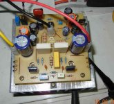
I did look at your picture you posted.
I see several questionable components
I did marked some of them.
Why do you have two pair driver transistor or what ever are those I marked with arrow? Red and blue.
You have two trimmer on your board (one for to get read of the offset??)
I do see to many caps on your board..
It is the best way to put the 10uF as close am possible at the power in and power transistors..
I posted my lay out 100% works. I will mark the component place soon.
Greetings G
Attachments
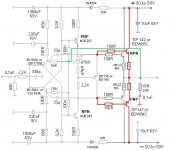
OK. There were no suggestions and so I'm going to use BC550/560 or BC546/556
, 2SC4793/2SA1837 and TIP142/147 . Bias Tr BD139.
Supply +/- 40 volts. ( With LS protection/relay )
If you mean the green marked transistor on the picture (Bias Tr BD139) that has to be BD136 or BD140 PNP and not NPN.
Please check that to
Thank you
Greetings G
Attachments
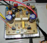
My layout with the caps, diodes, trimmer
I will post my layout with all the parts, probably that will help and encourage peoples who want to build the amp to use these layout.
It is tested & works how it should, proven layout!
I will mark all the parts place, now I started with the caps, diodes, and trimmer.
Soon I'll post the transistors location, after the resisters
When you print out the layout please set up your printer 110%, that mean increase the size of the layout by 10%.
These because some of the exotic components are bigger than the usual size.
Questions always welcome.
Greetings G
Attachments
Hi G,
I could not post a reply earlier as we lost power last night past midnight and it's mid summer here ! Lots of other catastrophes too last night. Two scopes died ! Don't know why but they are over 10 years old.
Also discovered that I had interchanged the NPN and PNP output power transistors on the amp board!
After that was fixed I discovered too late that another electrolytic was reverse connected and blew spectacularly just as I noticed it !
Then the power failed and I decided to call it a day !
I mentioned that I had used a capacitance multiplier and that's why there are two additional TO126 transistors and about 4 extra electroytic capacitors ! The extra preset is to set the offset voltage . The other one being for bias current. I can revert back to the basic circuit by shorting out what is not required. I built this board this way so that I could compare the stock circuit with the slightly modified one . Just so happened that I started off testing the modified version first. Doesn't affect the signal path , only the dc supply to the amp. The board was designed to fit the heat sink that I had and that's why it looks the way it does. It's still a bit larger than I wanted but that can wait. Ultimately if I build two channels I'll put the power supply and speaker protection on the board too. The heat sink will be different too.
Now I will have to sit down and fix the blown capacitor and try to find out why the scopes died ! One surely has a psu problem as it emitted 'blue smoke' after sizzling for a moment !
Today will be a very busy day ! There are tons of other things to do!
Last edited:
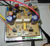
My layout with the semis, jumpers and emitter resisters
Hello
I do post the parts not the same time because it would be way to crowded the layout and that would cause confusion.
The green in these case the the Emitter resisters which goes under the PC board (or the copper side).
Because of that those have to be the last parts mounted to the board.
Jumpers are grey colored.
Greetings Gabor
Attachments
Very nice. Looks like you are using two pairs of output transistors. I've used only one pair on my board.
My emitter resistors are film types and very short , pin to pin, and so cannot be used as shown on your board. However it is interesting to see how you have arranged the parts. You might have noticed that I wanted to fix the board direct on to the heat sink and so the power transistors had to be located under the board. Not a good place for trouble shooting ! Even changing parts is a pain as everything has to be removed and care taken when mounting it all back on to the heat sink . My current board is about 95x95mm. Quite large for one channel !
My emitter resistors are film types and very short , pin to pin, and so cannot be used as shown on your board. However it is interesting to see how you have arranged the parts. You might have noticed that I wanted to fix the board direct on to the heat sink and so the power transistors had to be located under the board. Not a good place for trouble shooting ! Even changing parts is a pain as everything has to be removed and care taken when mounting it all back on to the heat sink . My current board is about 95x95mm. Quite large for one channel !
Up and running ! Great sound.
A quick update. Changed the blown cap and all is fine now. Offset adjusted to less than 1mV. Hasn't drifted by more than 1mV over a span of 2 hours but temp of heat sink has not changed too much either. Currently I can only get 60mA bias. The bias resistor has to be changed.
So on to the music. It appears to be VERY good ! On one channel it sounds great even with a protection resistor of 10 ohms in series with the power supply ! Will try it without the resistor as soon as I am sure everything is really fine. The bass sounds great while playing 'Sade'. On par with some other good amps here. But it might be even better without the protection resistor in the supply rail. Voice sounds very good and HF is extended without sounding clinical. Great potential. I'll have to get cracking immediately on a stereo board with two pairs of output transistors. I will try it with the capacitance multiplier removed and see what happens. Present load is a Behringer 2031B speaker.
G : This is a great sounding amp. Will make comparisons later with some other amps but as it is, it sounds great. Thanks for bringing this amp to our notice. Will rig up a stereo board with dual/single pair of power transistors.
LOTS of work now. Will have to try out the amp with LAT MOSFET also. Easy to switch between the two though the bias gets simpler with just a resistor.
This might turn out to be one of the best designs on this forum ! Can't imagine how great it would be with SMD parts. Should make the board really small .

Cheers.
A quick update. Changed the blown cap and all is fine now. Offset adjusted to less than 1mV. Hasn't drifted by more than 1mV over a span of 2 hours but temp of heat sink has not changed too much either. Currently I can only get 60mA bias. The bias resistor has to be changed.
So on to the music. It appears to be VERY good ! On one channel it sounds great even with a protection resistor of 10 ohms in series with the power supply ! Will try it without the resistor as soon as I am sure everything is really fine. The bass sounds great while playing 'Sade'. On par with some other good amps here. But it might be even better without the protection resistor in the supply rail. Voice sounds very good and HF is extended without sounding clinical. Great potential. I'll have to get cracking immediately on a stereo board with two pairs of output transistors. I will try it with the capacitance multiplier removed and see what happens. Present load is a Behringer 2031B speaker.
G : This is a great sounding amp. Will make comparisons later with some other amps but as it is, it sounds great. Thanks for bringing this amp to our notice. Will rig up a stereo board with dual/single pair of power transistors.
LOTS of work now. Will have to try out the amp with LAT MOSFET also. Easy to switch between the two though the bias gets simpler with just a resistor.
This might turn out to be one of the best designs on this forum ! Can't imagine how great it would be with SMD parts. Should make the board really small .
Cheers.
Hello
I'm happy your amp up and running!
I spent countless hours to match the components, parts to bring out from these amp the best..
Latter if you have time, energy you will realise these amp very-very sensitive and you can right away hear it when you replace a capacitor or transistor etc.
If you can find the BC550C/560C please replace the signal transistors.
I do have experience with capacitance multiplier PS from (ESP)Eliot web site.
All do I used in Class A amp like M Hiraga and Class A Hiraga I think it tend to sound a bit thin and clinical.
I do think it will be better with a good regular power supply min 4X10 000uF CRC set up KMH Nippon CC, Philips BC or other type of good caps without need to invest a fortune for them.
I would newer use Shamwa caps for audio but, I do want you to find out why .
Now I have these amp with power Lat Mosfet and also has another version where we invented some protection against drifting..
I didn't tested the modded circuit but I do not see reason for sound quality reduction.
I do love the mosfet sound but I think we never get the same deep bass from power mosfet in these circuit, based on my experience with mosfet.
Of course it has to be tested and proved.
For the input cap please try to use 2PC each mounted opposite direction.
I post the schematics for the modded darlington and LAT fet to.
I do has the lay out for both but again it was not tested yet!!!
Also you will get a lot of improvement after 50-100 hours burn in.
Enjoy your amp!
Greetings Gabor
Attachments
Hey G, the amp sounds really good as it is with Samwah caps too and a polyester cap at the input ! Bass is nice and punchy. The heat sink does heat up quite a bit when played loud. I haven't the time to sit and take a comprehensive set of measurements now. Maybe by the weekend.
Surely an amp that you can recommend to someone who wants an amp that's hard to beat easily. And if like you say , the parts are very crucial to how it sounds, better parts making it audibly better. Then all I can say is that with normal parts ( non audio grade !!) it sounds great ! I think the input cap will probably make the most difference. Generally speaking ( for the money ) polyprop caps sound better than most other caps ....best bang for the buck. Can try some X2 caps if they are polyprop types. These are easy to find. Some Chinese X2's are not good sounding ! I will try some botique caps when the stereo version is ready. I'm keen on trying out a discrete Darlington version. Not sure if I should do it on this board. Maybe I'll just keep it aside as a reference to compare against all variants !
Must check out dc offset stability and bias current stability. Maybe one should add non intrusive overload protection ! Like Apex ?
I set the offset to almost 0.000V ( 1mV min display). After a few hours it was +15mV. I was playing music loud all the while.
I must compare the amp with some others. The mind can play tricks easily ! But this is a VERY good amp. Hope it's dc stability will also be good.
I blew a pair of power transistors due to my stupidity. Replaced them and all's well again. Seems to clip gracefully. Sounds nice even when visibly clipped on bass notes. Listening to 4Play right now. Sounds great !
Later tonight I might try to do some comparison if the mains supply doesn't create problems like yesterday.
Bias transistor question ( Q9). Any special reason for using a PNP instead of a NPN ? I used a NPN ( BD139 ).
Last edited:
Hi G, why don't you tell me what brand /type of caps you want to use in the amp and power supply plus other parts ( like selected transistors for Hfe etc.) for it to be as good as you can make it. I'll build that and compare it with what I have now with ordinary parts. Should be an interesting exercise.
Did you find FET input transistors sound better than bipolar ? The Lat FET circuit has an advantage that it would be dc stable ! It's probably also fairly immune to shorts due to the high internal resistance of the device (?) . Since the circuit has NFB the internal resistance should not matter with regard to bass performance . Or did you 'compare' the Lat FET and Bipolar output devices and found a difference in the bass ?
Cheers.
Last edited:
- Home
- Amplifiers
- Solid State
- My first DIY amplifier 20 years a go