Hello
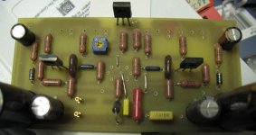
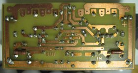
To those who wrote they would give a try to these darlington amp I'll post the layout before I will mod it to include wahab's mode.
The PC board size 112 X 56mm frame to frame , I advise to live some edge for mounting and if you use some exotic large size 1000uF 63V caps.
In that case cut the board done around 130 X 65mm size.
The lay out still remain the given size, all the parts feet very well.
I post the color codes but you have to figure it out the right place of the resisters.
Please pay att. at the input transistors -ECB- BC550/560, in my case JFet they are not face to face.
The 4 emitter resister goes under the PC board! Also the two 68K resister.
Take a look at the pictures.
To set up the bias
Adjust the trimmer to measure the highest R value between the two side of the trim pot (monted in the PC boards)...
After you connect your DMM between the PSU + and the PCB + measure mA or A --
Set up the bias to 100mA.. Please do not use speakers when you do any adjustment!!!
Leave the DMM there for a few hours until the amp warms up. Re adjust the bias after the warm up!
Please do not under estimate the heat sink size, that would lead to a thermal runaway 100% sure!
If you get any offset you can get read of if you chose right the input transistor matching the Hfe or choose a 100K multi turn trim pot (20X) as a adjustable resister, set up that 68K and and use that to replace one 68K resister. From the 68K please adjust that trimmer until you get read of the offset.
Take it out and measure the value of the trimmer and replace it with a resister..
You can always ask question, I'll be glad to help!")
Greetings Gabor
To those who wrote they would give a try to these darlington amp I'll post the layout before I will mod it to include wahab's mode.
The PC board size 112 X 56mm frame to frame , I advise to live some edge for mounting and if you use some exotic large size 1000uF 63V caps.
In that case cut the board done around 130 X 65mm size.
The lay out still remain the given size, all the parts feet very well.
I post the color codes but you have to figure it out the right place of the resisters.
Please pay att. at the input transistors -ECB- BC550/560, in my case JFet they are not face to face.
The 4 emitter resister goes under the PC board! Also the two 68K resister.
Take a look at the pictures.
To set up the bias
Adjust the trimmer to measure the highest R value between the two side of the trim pot (monted in the PC boards)...
After you connect your DMM between the PSU + and the PCB + measure mA or A --
Set up the bias to 100mA.. Please do not use speakers when you do any adjustment!!!
Leave the DMM there for a few hours until the amp warms up. Re adjust the bias after the warm up!
Please do not under estimate the heat sink size, that would lead to a thermal runaway 100% sure!
If you get any offset you can get read of if you chose right the input transistor matching the Hfe or choose a 100K multi turn trim pot (20X) as a adjustable resister, set up that 68K and and use that to replace one 68K resister. From the 68K please adjust that trimmer until you get read of the offset.
Take it out and measure the value of the trimmer and replace it with a resister..
You can always ask question, I'll be glad to help!
Greetings Gabor
Attachments
Last edited:
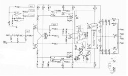
With your mode using those zeners and 40V rail voltage can I stick with the BC550/560C pair??
The emitters of theses transistors are defined by their base voltage
and as such they will be at +- 0.7V for the PNP and NPN respectively
while the collectors are almost at -+40V respectively minus two volts
drop across the VAS emitter/base junction and emitter resistors ,
that s still about 38V to withstand , quite close to the max ratings.
Also I need to know the 220uF V rating. Before 16V was more than enough..
The reason those are special low noise signal transistors.
The voltage across theses caps barely reach 1V , so even 10V models
are already overkill voltage wise but AC wise they are part of the amp
negative feedback loop and as such will define the low frequency cutoff.
With 220uF the gain has decreased by 13% at 20Hz compared to 1Khz,
so this is the lower recommended value , the original japanese schematic
use 1000uF.
When I was looking for the orig BC414C/416C which became obsolete I did tried a lot of transistor there but nothing did the job good as the BC550C/560C.And I was informed the 414C/416C was replaced by the BC550C/560C which has a bit higher voltage but lower Hfe.
In one word I would like to keep the BC550C/560C at the input. Knowing that those transistors are still OK I can swap them to JFet to.
With JFet I get in the mids area more neutrality, more air between the instruments.
There are a lot of equivalent devices in the BC series for 45V Vce but
such devices with C rating (gain > 420) are relatively rare.
The BC550C/560C have gain as high as the 414C/416C ,
they are in fact the same devices but from different manufacturers.
The best possible devices are the very one on the japanese schematic ,
120V 2SA872A/2SC1775 , while the 120V 2SA992/2SC1845 are valuable
replacements.
As for Jfets , in simulations they do no better but i ll take a second
look just in case i missed something in early sims.....
R28 that symbolize the speakers load?
Yes , that s it.
I repost this stabilized version , it is likely the one that will help get rid
of most misbehaviours and , i hope , end all the time waste devoted by
builders to this schematic.
Nice amp, Wahab! Better than what I have built I believe.
I gave up because of the high class-A bias. Yours is half of my bias but achieved similar result (with my own transistors). I will soon give it a try because I want to use TO-220 output devices.
Attachments
The emitters of theses transistors are defined by their base voltage
and as such they will be at +- 0.7V for the PNP and NPN respectively
while the collectors are almost at -+40V respectively minus two volts
drop across the VAS emitter/base junction and emitter resistors ,
that s still about 38V to withstand , quite close to the max ratings.
With 220uF the gain has decreased by 13% at 20Hz compared to 1Khz,
so this is the lower recommended value , the original japanese schematic
use 1000uF.
The best possible devices are the very one on the japanese schematic ,
120V 2SA872A/2SC1775 , while the 120V 2SA992/2SC1845 are valuable
replacements.
As for Jfets , in simulations they do no better but i ll take a second
look just in case i missed something in early sims.....
QUOTE]
Hello
That would be bad if I have to start to search again for input transistor.
I have another option, to lower the rail voltage.
I have 2PC 25V Xformer, that gave me 36V rail. Will build it as a mono block these amp.
A bit would be a bit stupid to lose some power because $1 value transistors..
I know well the 2SA872 & 2SC1775..
I have at home at least 30PC 2SA872 but the 2SC1775 hard to find device.. And has different pin out.
These transistors are popular from the Hiraga...
What about 2SA970 & 2SC2240 from Toshiba, I have BL grade at home......
Wahab
now we mode the front and the input transistors will receive higher voltage if I understood that well.
Do that influence the power of the amplifier??
If you advise bigger caps for the 220uF I can test that to..
Hope these mode will not degrade the sound of the amplifier at all.
One of the main reason I want to stick to the well known & tested transistors.
I modified the layout after your circuit.
One more time thank you very much!!
With the FET the amp has better mid-range, become more transparent and natural.
Not just after my ear, other people wrote similar about.
All do some people say it does decrease the dynamic and the deepness of the bass a bit.
Thank you one more time
Greetings Gabor
Attachments
Last edited:
What about 2SA970 & 2SC2240 from Toshiba, I have BL grade at home......
2SA9702SC2240BL should suit perfectly but if ever the amp yield higher output DC offset than the BC550C/560C then stick with the BCs but make sure that your PSU voltage will never be more than +-45V.
now we mode the front and the input transistors will receive higher voltage if I understood that well.
No , the voltage across the BCs is the same as with the original amp , this is unchanged.
If we take the original schematic as exemple , one can reduce the 68K almost as much as he wants, this wont change the emitters voltages wich will stick at close to +-0.65V , hence only the current through the said resistor and by consequence through the transistors will increase , not the voltage.
Of course , if this current is increased this way , this same current will forcibly yield a higher voltage across the 3.3K that load the collectors , hence the VAS will see a higher voltage at its base thus increasing its collector/emitter current.
Do that influence the power of the amplifier??
Indirectly , but to a very small extent.
You can see that the VAS emitters resistors have been reduced from 330R to 180R.
I had to procede this way because the 100K resistors that once provided an additional current of 0.4mA (that is added to the 0.58mA coming from the input stage) through thoses 3.3K resistors are no more here , so the voltage at the VAS bases is a little less , hence there is slightly less voltage at their emitters so the 330R are reduced to restore the initial 5.6mA VAS current.
Of course , the voltage across theses 180R is still high enough , about 1V , to make sure thermal variation of the VAS wont change it significantly , but a consequence is that the voltage loss in the VAS is reduced by about 0.85V and as much , or rather little , is gained for the max output voltage of the amp compared to the orinal that had higher voltage loss.....
If you advise bigger caps for the 220uF I can test that to..
You can keep the current value for first tests and if swapping the things ,
just take what you have at hands , no need to buy anything.
With the FET the amp has better mid-range, become more transparent and natural.
Dont know but keep in mind that the voltage is about 40V and Jfets dont like
such high voltages that s why they are always cascoded once the voltages goes higher than 15 or so volts , as in Hiraga s design.
Nice amp, Wahab! Better than what I have built I believe.
I gave up because of the high class-A bias. Yours is half of my bias but achieved similar result (with my own transistors). I will soon give it a try because I want to use TO-220 output devices.
Thanks Jay , although that s not my amp but rather some
schematic that goes through the forums checking the audio
crowd patience and nerves....
The perfs are quite correct but notrhing exceptionnal , i guess
that it would have been a good amp back in 1972 or so...
The bias i used in sims was 100mA/pair , with a total of two pairs
of BDW93C/94C , adequate for a +-40V PSU and 8R only speakers ,
but 60mA/ pair should be enough given that the total current is 120mA.
The most bothering is DC offset stabilty with temperature.
The original schematic has about 40mV variation for 60°C
variation in active components temperature , while the modded
one do a little better with a 16mV variation in the same conditions ,
still an order of magnitude worse than an average differential input amp...
The perfs are quite correct but nothing exceptionnal , i guess
that it would have been a good amp back in 1972 or so...
May be nothing exceptional. But people willingness to accept the temperature stability issues, implies that something worth the hassles, no?
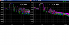
I think the FFT graph (almost) reach the position where good or bad is not only in the graph but lay somewhere mostly in "unknown" places. I simulated using BF469/470 in the VAS which I believe is inferior than your chosen transistors.
The most bothering is DC offset stabilty with temperature.
The original schematic has about 40mV variation for 60°C
variation in active components temperature , while the modded
one do a little better with a 16mV variation in the same conditions ,
still an order of magnitude worse than an average differential input amp...
Yes, this issue has been discussed deeply on the SSA thread, where Lazy Cat (and others too) has shown some solutions. I use BF469/470 because I think the PNP matches the NPN better than in most other transistor pairs, a condition that is needed in this (simple symmetrical) topology.
2SA9702SC2240BL should suit perfectly but if ever the amp yield higher output DC offset than the BC550C/560C then stick with the BCs but make sure that your PSU voltage will never be more than +-45V.
Dont know but keep in mind that the voltage is about 40V and Jfets dont like
such high voltages that s why they are always cascoded once the voltages goes higher than 15 or so volts , as in Hiraga s design.
Hello
I will never go over with my PSU 40V.. I have several 27.5-0-27V transformers, I'll use those.
That gave me 40V rail voltage..
Each transformer rated 225VA so for mono block each it will be great.
I will test again the JFet with my lower PSU I do compare the BJT again with the JFet
With 36V the JFet worked great, I think it has lo power there, few mA..
I do have some 2SJ103BL/2SK246BL JFet, those are 50V all do those are not direct replacement for the 2SJ74BL/2SK170BL..
I made the black lay out ready, if someone want to use it please open with paint program page set up 110% and print.
Now these amp designed probably at seventies..
You can order the NCC200 (upgraded NAIM clone) from UK, very popular great sounding amp.
I did compared these darlinton with that amp..
Just different level in any aspect! All do I like that amp sound to..
I built amps like Symasym, Aleph30 just to mentioned some modern and famous amp..
Not even kept those.
Also built the Hiraga Class A with the orig transistors and I didn't kept that to, that has some common with these amp despite one is Class A the darlington only Class A/B...
Greetings Gabor
Attachments
You can order the NCC200 (upgraded NAIM clone) from UK, very popular great sounding amp.
I did compared these darlinton with that amp..
Just different level in any aspect! All do I like that amp sound to..
I built amps like Symasym, Aleph30 just to mentioned some modern and famous amp..
Not even kept those.
Usually I understand people preference/taste with sound. But you are an exception. I don't know what it is that you like and what it is that you don't. Of course, because you're not a beginner I assumed that you know about the effect of MATCHING. I mean, amplifier is only a small part of the audio chain. It took me years to be confident in localizing or determining the real location of the perceived sound issue in the audio chain. That's probably because I have played in all chains from digital to loudspeaker design.
I believe in voodoo, but I don't believe in voodoo in audio. Everything I believe can be explained with Physics. It is just our knowledge in Physics that is so limited. But at least, I can correlate perceptions with "numbers" (and I know psychology more than audio/electronics, if you know that it has relationship with audio).
In this symmetrical topology, when in class-A, HEXFET output is the best imo. Also proven by numbers and ears.
Also try building the Aleph J Babelfish if you haven't
(high bias class-A). Nothing in that amp that is bad (if you believe in "numbers", because we may have different "taste", it is on paper better than any class-A amps you have mentioned): simplicity wise, measurement wise and subjective perception. There are big room for "experimentation" with parts to get the most out of it.Gaborbela, here are two circuits. The first is a commercial design which was very popular in europe and recieved very high acclaims for its sound. Most reviewers claim was that no distinguished difference can be heard between it and a top notch tube amp. Youll also notice that the design is 100 % based on the original JLH except use of the mosfets as vas. It has none of the shortcomings of your circuit, bias stability is rock stable, as you can see it it was cleverly taken care of although it costs two more transistors and a couple of resistors. Servo was placed to take care of DC offsets and its a class A design. some models used two output devices for higher power, also note the dual feedback as in your schematic. Its part why the amp sounds the way it does.
The second circuit is capable of very low distortion, around .007 with good parts and also stable but this one is class AB. Here the bias stabilty is obtained through other means, it s as simple as it looks.
I can post more models as recent as 2004 using this circuit but here the sound does change somewhat as cascodes are introduced to achieved super low distortion figures. Seems like old 1972 technology is just fine judging by the great reviews the first amp in particular got.
Attachments
The emitters of theses transistors are defined by their base voltage
and as such they will be at +- 0.7V for the PNP and NPN respectively
while the collectors are almost at -+40V respectively minus two volts
drop across the VAS emitter/base junction and emitter resistors ,
that s still about 38V to withstand , quite close to the max ratings.
With 220uF the gain has decreased by 13% at 20Hz compared to 1Khz,
so this is the lower recommended value , the original japanese schematic
use 1000uF.
The best possible devices are the very one on the japanese schematic ,
120V 2SA872A/2SC1775 , while the 120V 2SA992/2SC1845 are valuable
replacements.
As for Jfets , in simulations they do no better but i ll take a second
look just in case i missed something in early sims.....
QUOTE]Why the red type and why can't the Forum's "quote" system be used?Hello
That would be bad if I have to start to search again for input transistor.
I have another option, to lower the rail voltage.
I have 2PC 25V Xformer, that gave me 36V rail. Will build it as a mono block these amp.
A bit would be a bit stupid to lose some power because $1 value transistors..
I know well the 2SA872 & 2SC1775..
I have at home at least 30PC 2SA872 but the 2SC1775 hard to find device.. And has different pin out.
These transistors are popular from the Hiraga...
What about 2SA970 & 2SC2240 from Toshiba, I have BL grade at home......
Wahab
now we mode the front and the input transistors will receive higher voltage if I understood that well.
Do that influence the power of the amplifier??
If you advise bigger caps for the 220uF I can test that to..
Hope these mode will not degrade the sound of the amplifier at all.
One of the main reason I want to stick to the well known & tested transistors.
I modified the layout after your circuit.
One more time thank you very much!!
With the FET the amp has better mid-range, become more transparent and natural.
Not just after my ear, other people wrote similar about.
All do some people say it does decrease the dynamic and the deepness of the bass a bit.
Thank you one more time
Greetings Gabor
Hello
Adrew please take a look the orig post again, I did used quote but for some reason it didn't came out usually the lighter blue background.
So not to delete all post and re write it and re post it again. Only option I had pick some other color so people can see that is a quote.
I hope that is not against the rule of the forum.
If yes I apologise.
Greetings Gabor
Usually I understand people preference/taste with sound. But you are an exception. I don't know what it is that you like and what it is that you don't. Of course, because you're not a beginner I assumed that you know about the effect of MATCHING. I mean, amplifier is only a small part of the audio chain. It took me years to be confident in localizing or determining the real location of the perceived sound issue in the audio chain. That's probably because I have played in all chains from digital to loudspeaker design.
I believe in voodoo, but I don't believe in voodoo in audio. Everything I believe can be explained with Physics. It is just our knowledge in Physics that is so limited. But at least, I can correlate perceptions with "numbers" (and I know psychology more than audio/electronics, if you know that it has relationship with audio).
In this symmetrical topology, when in class-A, HEXFET output is the best imo. Also proven by numbers and ears.
Also try building the Aleph J Babelfish if you haven't
Hello Jay
I think it would take a lot of time to explain the sound I like it or what I don't..
I wrote something about already to you.
Yes I believe and I know the chain MATCHING and I know is very important!
Also I believe the weakest part of the chain has lot of to do with the achieved sound quality.
I do not believe in voodoo in audio also but I believe the components quality etc is important not just a great circuit..
But in a bad circuit waste of money to spend on exotic parts.
I have the Babelfish PC boars but until I collected the parts Mr Pass it came out with the Aleph J.
One of the think I hate when you have to imagine the bass or to soft, or uncontrolled etc. I like deep bass, well controlled, not rounded...
Mid-range has to be natural, well articulated, airy, transparent, instrument well separated etc
Highs not to be sharp, metallic.
I hate muddy sound, also most Japanese amp like Technics, Pionieer mostly all new stuff nothing to me. Old Marantz, Kenwood, Luxman, out of the commercial stuff some of them where better than today many commercial stuff.
I have a Nacamichi receiver and I use it a lot.
I do like the Pass amplifiers (I do have a Aleph X and I like it) but the A30 was a bit dark and week in bass!
If you read my post you quoted you can see I do like the NCC200 sound but that is a clone I worked on close to 4 month.
To bring out the best sound, need to match the parts to each other, time also a factor. I do believe components in burn in but that not make a bad sound acceptable..
I have all the component, stuffed PC boards for a Aleph2, and I want to test the F5 T with Toshiba mosfets.
May be to you hard to believe it but I built and tested over 100 DIY amp and clone..
Many of them like SEWA, Symasym, Aleph30, so on just was waste of time money, energy.
All those amps where built exotic parts.
I use Kimber 8TC speaker cable, Siltech IC cable of course I have others to.
I spent close $$$$ on silver , 24K gold wire, and other wires..
I use Audio Alchemy CD player, Luxman CD player, Rotel, Kenwwod old top of the line and a Meridian DAC.
TT I have several but usually I use my Elac, Kenwwod KD 500 marble base about 41LB.
I use mostly Shure V type 3,4 and micro gr..
I have several other cartridge to.
I will build a DIY turntable from DUAL Idler derived TT I will build solid enclosure from Baltic Birch and I will DIY the arm to..
That is sometimes in the future.
The last 20 years I built speakers for me and sometimes people ask to sell to them..
I do have good brand commercial speakers but DIY speaker must!
To explain I built the Profet amp (similar to the F5 with Hitachi laterals)
I used in a small room, I do like it a lot so I invested a lot of money on Caddock resisters ($6-7/each) Exicon mosfet, Cardas hock up wire and I wanted to bridge it to get 50W.
After a few month I finished the Darlington amp and the NCC200.. After I started to use those to burn in I could not listen anymore the Profet.
Now I invested a couple hundred Dollars in vain,,,in to the Profet.
Also one of my friend built the Profet, I sent the kit to him. He like it a lot to and everybody heard that amp they like it.
You know when something so much better you can't go back (done) 2-3 level to start to listen that amp..
I had a small Philips SE tube amp, I rebuilt it sounded OK but only 2W.
So i took out the good Siemens ECC83 tubes and the Telefunken EL95.I used cheaper tube and I sold it on Ebay to USA.
The guy was so happy with that but those tube I took out degraded the amp very badly and he still like her a lot.
I made A/B test, and always I do when I think the amp ready..
A bad sounding amplifier even in good chain will sound bad actually easier to realise how bad is.
A good amp even in the week chain bring extra improvement!
Greetings Gabor
Hello gaborbella ,
Can you say how is the sound of this amp compaired to other ones(for example, gainclone"my audiophile approach" Lme3886+Lm318 or pass F5,class T or whatever have you listen) ?
Is this the best for you ?
I was thinking at the same topolopgy only that my wish is to not build with darlingtons but with cfp like the Elliot P3A project : http://www.diyaudio.com/forums/atta...4796794-cfb-cfp-amp-development-simplecfb.jpg
Thank you !
Last edited:
Hello
Interesting that power stage!
Can you post some sim result if you run please.
Thank you
Also please test the orig amp to, all parts a cheap, I posted the layout earlier..
I forget to warn you the two circuit I posted last time are different, they have different feedback and some other change to.
Originally I built the one where second pair power darlington drawn red.
Red because if U use only 30V PSU U really don't need to parallel them.
All do the amp very sensitive to the component quality are used I can ensure you you will be amazed even with the cheap 10C resister..
Greetings Gabor
Hi Gabor
probably I was wrong regarding lowering THD at about 10dB, the simulations showed similar values and harmonics behavoiur to the original circuit.
I cannot promise that I will play with the simulations later.
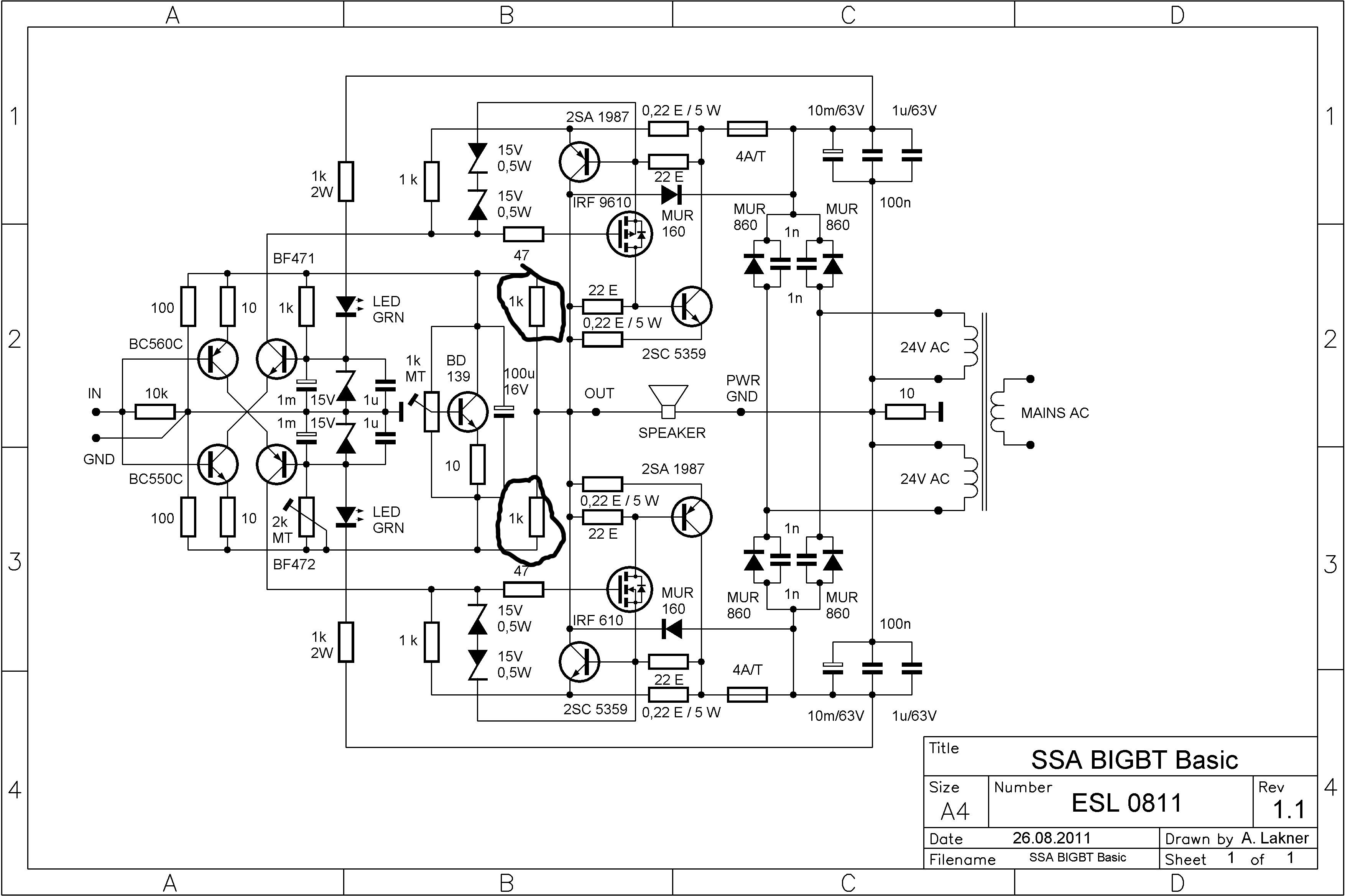
This OP stage was taken from Lazy Cat's SSA http://www.diyaudio.com/forums/atta...ical-amplifier-ssa-bigbt-basic-1.1_zadnji.jpg . It has very high input impedance which is not loading to the vas.
Hello gaborbella ,
Can you say how is the sound of this amp compaired to other ones(for example, gainclone"my audiophile approach" Lme3886+Lm318 or pass F5,class T or whatever have you listen) ?
Is this the best for you ?
I was thinking at the same topolopgy only that my wish is to not build with darlingtons but with cfp like the Elliot P3A project : http://www.diyaudio.com/forums/atta...4796794-cfb-cfp-amp-development-simplecfb.jpg
Thank you !
Hello
Please forgive me I'm just tired and has that feeling there is no reason to talk or write about the sound quality of the these amp any more.
I did it so many time .........................................

I wrote so many comparison about these amp I think no reason one more.
Those who interested and want a great sound please give a try.
To those who build amps (has transformers, heat sink etc) it cost a few bucks to test these amp!
Greetings Gabor
Excuse me Gabor ,I have finished to read the hole 22 pages.Hello
Please forgive me I'm just tired and has that feeling there is no reason to talk or write about the sound quality of the these amp any more.
I did it so many time .........................................
I wrote so many comparison about these amp I think no reason one more.
Those who interested and want a great sound please give a try.
To those who build amps (has transformers, heat sink etc) it cost a few bucks to test these amp!
Greetings Gabor
Now I get it .I will try to mod a little the amp to have more stable bias current with temp and also with supply .Thank you !
Excuse me Gabor ,I have finished to read the hole 22 pages.
Now I get it .I will try to mod a little the amp to have more stable bias current with temp and also with supply .Thank you !
Basicaly , this schematic is the one that Lazy cat used for his SSA ,
the only difference is that he cascoded the input stage , wich do not
improve the perfs at all compared to the basic version.
There s really not much more that can be done to improve the thing
of this circuit beyond what has been posted in the last pages of this thread
without going in complexities that will often yield zero benefit.
According to simulations the version at post 197 has the best stability
DC offset and quiescent current wise.
Perfs can be improved slightly but at the expense of theses parameters.
Simulations are limited in their ability to show problem spots, the vas standing current will be very unstable leading to unstable output transistor biasing as will DC offset until you sort out the input transistors tempco.
Much can be done to improve performance, another pair of transistors can drop THD20 to .005 at full power below clipping
Much can be done to improve performance, another pair of transistors can drop THD20 to .005 at full power below clipping
the vas standing current will be very unstable
How will it be unstable ??.by wich mechanism that a simulator couldnt spot.??..
Also , keep in mind that we re talking of the circuit in this thread ,
not eventual versions that you perhaps has trouble with.
Last edited:
- Home
- Amplifiers
- Solid State
- My first DIY amplifier 20 years a go