The 4.7R resisters has to around 20W?? otherwise with the resister temperature will change the measured V which would change by the warm up..
Can I use my 16V PSU here??
Yes , a 16V PSU is adequate as well.
The 4.7R resistor will dissipate about 2.5W whatever the PSU
but with 16V the transistor dissipation will rise to 8W.
More like a good tube amp.
Has some warmth in it but the bass does not get rounded, a la many mosfet or tube amp, it remain precise. Deep and everything well separated. Sometimes I feel I can reach out to hold the hand of the singer etc.
Like he or she would be at front of me in my room.
Honestly very very hard even to imagine I can build a better sounding amplifier like these.
We compared these with serious amplifiers, not even came close either of them..
I feel my audio hunger will be satisfied or fulfilled if I succeed to put these amp together in a way to keep the orig sound with out any degradation and make it reliable and stable..
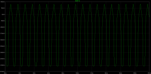
I suspect that this "warmth" and "tube" like sound is due to high distorsions ,
particularly intermodulation wich is at least 0.3% for 400HZ + 7KHZ 1:4 ratio test, and about at the same level that "good" tube amplifiers..
The effect of the 100K resistors influence goes beyond DC operating conditions as the resulting low global feedback has trouble removing intermodulation products.
For info , 400HZ + 7KHZ 1:4 ratio IMD is simulated below for both the original amp and for the modded version that get rid of the said 100K.
I let you imagine the picture with more than two frequencies , wich is the case for music...
Attachments
The Sankens. So where's the model?
Sorry , i have none for darlingtons , only for single power transistors.
I guess that their darlingtons can be simulated using their power devices
models and a driver that is fast enough , the typical internal resistor being
about 70R according to their datasheets.
Hello
Thank you wahab
I read your sim result, the modded amp is referring to the circuit you posted a few days a go?
I don't know if it would be a big request to compare the sim with a popular amplifier like the F5 or any other popular amp.
I mentioned the F5 because U used that to compare to the Hitachi mosfet amp to. Also I have some interest on that the F5 T with Toshiba mosfets...
The amplifier can have higher distortion then usually the BJT amplifiers but I can't hear that.. I heard way more distortion from P Daniel Gain clone premium kit.
Low distortion not all when we talk about a great sound, many Japanese amp has 0,0003 etc. The famous Symasym has very low distortion and I couldn't listen that amplifier... Not bad just not my cup of tea..
I can't measure it since that would need min a good scope etc.
We did compare these amp (the first build at Budapest) to a famous 845 SE tube amp.
That amplifier cost a arm and a leg designed an built by a well known Hungarian engineer who built tube amplifiers for living all his life.
The result was incredible to the favour of the Darlington.
I believe some of my mode I had done in the circuit it took the amp into another level soundwise.
Yes it became less stable but I do not give up on her.
Again I hope someone soon give a try to the amp so further talk about the sound quality it will be unnecessary.
Greetings Gabor
I had to smile at this, because I feel the same way at times. Of my solid state amps, it's the first one I made that is still used everyday. I made others but I like the sound of the first one. I also rebuilt it with better parts and it is also based on an old and simple design that sounds great, RCA 1970 / AKSA. I am also trying to build less and enjoy the results more.
I did make a symmetric design, I called it "TGM5" and it is described in a thread around here somewhere. Like most symmetric VAS designs the VAS current is ill-defined and so the output bias is ill-defined. I used a lot of VAS emitter degeneration (as used by Bryston in their 2BST) which reduces VAS current instability. On top of that I used a simple Vbe multiplier circuit from Hagerman that is far less sensitive to any remaining VAS current variation. When combined these techniques produced stable bias. You can use the same solution.
I have to say that it's really nice to read your posts because of how you express your feelings about your project. I feel that I should build your amplifier !
Hello Bigun
Welcome here.
I did follow your thread about the TGM5 amplifier.
It is a nice design. I can say you build and test amplifier so fast I think nobody on the forum.
If you could share your first amplifier circuit with me I would appreciate it.
In case if you do not want to post on the forum please send a PM to gaborzoltan2@gmail.com
I ask because I do like many of your design..
Greetings Gabor
Have had some time now to look around in the eldest boxes in my workshop.
Resulted in completion on a RIAA-amp I made some 33 Years ago.
That is, I have ordered new PCBs for it.
The prototype I had only for a few weeks. It ended up in my professors stack of HiFi equipment, and was paid for by giving me a straight A for my effords.
Also there was some drawings for a 2X50W sanken hybridamp I built for my sister.
Some poweramps and a QUAD33 Clone is alsi in there.
And the most fun of all, When attending what would de College in US, I built a small amp were we was making the transformer ourselves, making the chassis ourselves, the PCBs was handmade. I plugged it in, and it worked just like I remembered it did back then.
Has been going around to most of my family, and never been repaired. I build quality-amps is what I try to say
There is so many started-not finished projects there.
Think I should finish them and see what has happened to the sound over all those years. . Humming down memory lane here.
Member
Joined 2009
Paid Member
If you could share your first amplifier circuit with me I would appreciate it.
Thanks for your kind words !
No secrets about my first design - it is not really mine, but RCA 1970, AKSA, DX and many others showed the way before me. But is the design that brought me into this hobby. It was all very mysterious and very interesting to me.
http://www.diyaudio.com/forums/solid-state/140461-tgm-amplifier.html
Hello
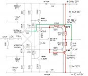
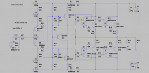
Wahab here is modded version of my Darlington.
Feedback taken only from the input transistor (in my case JFet), the 100K resister and the 2PC 33pF was moved to the VAS.
Probably with these mode the amplifier will be more stable. I'm not sure if these degrade the sound, it would be great to know.
If the sound would remain the same I would mode the layout to and I would test it.
I have to go anyway to do laser printing for the Hitachi mosfet amplifier, I added the latest mode to the layout.
Before I start the etching of PC board it would be great to have your opinion about these mode.
Would you be so kind please take a look at one more time. I promise I do not disturb anymore with these amplifier.
Thank you very much!
I att: the old circuit to so you can have at your hand.
Greetings Gabor
Attachments
hello
I tried to make some sims with ltspice
and it was impossible to find the models of the darlingtons. Instead of this I used hybrid darlington made of MJE15032/3 + MJE3281/1302.
but the simulations are strange
please tell what should be done to make this amp ok?
thank you in advance
Attachments
Hello
When you try to run some sim please look for the next darlinton pairs
BDW83C BDW84C
TIP142 TIP147
BDW93C BDW94C
BDX53C BDX54C these Darlintons are all good if U chose the right PSU
May be you find some model of the other two pair darlington
If not that is the big problem
I tested the Hybrid darlington in real life and sounded horrible
I spent weeks on tests and after I gave up. Even my best result had a huge sound difference in the favour of the cheap $2-3 darlington like night and day
My advise
Use only one pair hybrid darlington.
R1 must be much higher 7 to 10K
R2 has to be lower 40R or 25R
Now these darlingtons has a built in diode, I'm not sure but probably that is important to.
You must pick the right transistor to get close the same gain,speed, capacitance etc like one of those darlington pair
It is a big mistake to pick any two transistor to build up the darington
You must calculate the mentioned req.
Also you can take a look at MJ11015/16 darlinton....
I hope these help
Greetings Gabor
gaborbela, I like your amp, I built a very similar circuit 20 years back when still in varsity. At the time I had some correspondence with JLH himself who was the original author of the circuit back in 1960s. Indeed this circuit can sound very good.
What I dont understand is why you want to mod it if youre happy with the sound and it works ??. I see some potencial problems that can easily be cured to a large extent, just see how JLH used the circuit. Its best suited to class A and sounds great using two output pairs in class A without drivers. The dual feedback is part of the reason the amp sounds good although not used by JLH but similar sound can be had without it. A servo can also be implemented to better dc offsets if you having problems with it.
The only mod I would do to it is using either a baxandall super pair (my prefered choice back then) or the hawksford cascode on the vas to lower distortion a little and doesnt change the sound signature that much.
If youre interested I can post some versions that were commercially available and were renowned for their good sound, always described as tubey. Some even use mosfets as vas.
Input NPN and PNP at the wrong place (PNP should be above)
thanks Jay
this was it
Hello
When you try to run some sim please look for the next darlinton pairs
BDW83C BDW84C
TIP142 TIP147
BDW93C BDW94C
BDX53C BDX54C these Darlintons are all good if U chose the right PSU
May be you find some model of the other two pair darlington
If not that is the big problem
I tested the Hybrid darlington in real life and sounded horrible
I spent weeks on tests and after I gave up. Even my best result had a huge sound difference in the favour of the cheap $2-3 darlington like night and day
My advise
Use only one pair hybrid darlington.
R1 must be much higher 7 to 10K
R2 has to be lower 40R or 25R
Now these darlingtons has a built in diode, I'm not sure but probably that is important to.
You must pick the right transistor to get close the same gain,speed, capacitance etc like one of those darlington pair
It is a big mistake to pick any two transistor to build up the darington
You must calculate the mentioned req.
Also you can take a look at MJ11015/16 darlinton....
I hope these help
Greetings Gabor
thank you
I like your amp, probably will build according to your schematic and part but with TMC.
I tried to experiment with it
added op stage like bigbt (Lazy's)
and TMC feedback type
correct me if I am wrong, THD decreased ~10dB and the spectrum is nice descending
Attachments
gaborbela, I like your amp, I built a very similar circuit 20 years back when still in varsity. At the time I had some correspondence with JLH himself who was the original author of the circuit back in 1960s. Indeed this circuit can sound very good.
What I dont understand is why you want to mod it if youre happy with the sound and it works ??. I see some potencial problems that can easily be cured to a large extent, just see how JLH used the circuit. Its best suited to class A and sounds great using two output pairs in class A without drivers. The dual feedback is part of the reason the amp sounds good although not used by JLH but similar sound can be had without it. A servo can also be implemented to better dc offsets if you having problems with it.
The only mod I would do to it is using either a baxandall super pair (my prefered choice back then) or the hawksford cascode on the vas to lower distortion a little and doesnt change the sound signature that much.
If youre interested I can post some versions that were commercially available and were renowned for their good sound, always described as tubey. Some even use mosfets as vas.
Hello
I do not try to improve the sound and I will do everithing to keep it how sounded!
I only try to make the amplifier a bit more stable.
Not because is unstable but I want to fell I can avoid the speaker protection.
I pushed the amp to hard when I replaced the 0R47 emitter resister with 0R22 but I get a great dynamic increase and now I do not want to go back.
Actually at my last test it was my fault the amp got in to thermal runaway.
I set up the bias 250mA and after 2 hour listening I felt sleep.
About 6 hours latter I heard some noise I woke up and some parts of the amp went up into flame.
Emitter resister was red, the CRC PSU 10W resister was red, one darlington burned into charcoal, huge hole around the transistor on the PC board..
I would like to avoid these but again I do not want to compromise the sound I got..
Again the main focus to keep the sound and make it a bit more stable.
Also my heatsink was to small last time. Now I ad 3-4X as big.
About the amplifier sound 100% I agree how you describe it!
Far the best amp I ever built or heard in my system.
Thanks for your comment and if you have at hand or you find info about the amp you wrote please posted here.
Thanks one more time
Greetings Gabor
Last edited:
thank you
I like your amp, probably will build according to your schematic and part but with TMC.
I tried to experiment with it
added op stage like bigbt (Lazy's)
and TMC feedback type
correct me if I am wrong, THD decreased ~10dB and the spectrum is nice descending
Hello
Interesting that power stage!
Can you post some sim result if you run please.
Thank you
Also please test the orig amp to, all parts a cheap, I posted the layout earlier..
I forget to warn you the two circuit I posted last time are different, they have different feedback and some other change to.
Originally I built the one where second pair power darlington drawn red.
Red because if U use only 30V PSU U really don't need to parallel them.
All do the amp very sensitive to the component quality are used I can ensure you you will be amazed even with the cheap 10C resister..
Greetings Gabor
Last edited:
Wahab here is modded version of my Darlington.
Feedback taken only from the input transistor (in my case JFet), the 100K resister and the 2PC 33pF was moved to the VAS.
Probably with these mode the amplifier will be more stable. I'm not sure if these degrade the sound, it would be great to know.
If the sound would remain the same I would mode the layout to and I would test it.
I have to go anyway to do laser printing for the Hitachi mosfet amplifier, I added the latest mode to the layout.
Before I start the etching of PC board it would be great to have your opinion about these mode.
r
Hi Gabor ,
This connection of the 100K resistors will change nothing in respect
of iddle current stability vs supply voltage variation since the VAS collectors
are exactly at the output potential +-Vbe of the respective transistors.
That is for DC currents stability.
For AC behaviour ,the feedback from collector to base of the VAS will linearize
only this stage contrary to the original version , hence distorsions of all kind
will be likely higher.
As for moving the 33pF caps the designer was smart at least on this aspect and changing
their connection will degrade phase response.
The 100K resistors implementation as well as feeding the input stage
through 68K resistors that goes directly to +-VA are both two major
flaws of this design and it s just impossible to get DC stability by keeping
them in place as they are currently , either in the original or in this modded
version.
I benefit from this post to point a problem already noticed by Rod Elliott
in his site , that is , designs or bad habits that are to be avoided.
There s scores of non mature designs hanging in the web and regularly
they are picked by some innocent guys that just dont know the trouble
they will experiment because a designer has made a design while negligating
some parameters that may have appeared as non significant at first thought.
The consequence is huge time quantity lost by lots of people debugging again and again
what could have been easily fixed from the start.
So it goes for this amp , if you want to use it as it is then you ll have
to provide the front end with fully regulated ans stabilized rails.
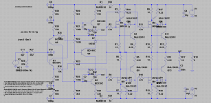
Rather than going this complexe route i proposed to get rid of the 100K
wich are creating trouble while having no benefit in perfs , quite the contrary,
as well as replacing each 68K resistors by two resistors with a zener , wich will
make sure the input stage current will remain stable whatever the supply voltage.
In simulations the original version has iddle current variation of 4% per %
in respect of supply voltage variation , meaning that if the supply voltage
increase by 10% then the iddle current will increase by 40%.
In the modded version with zener the same 10% supply variation will
yield only 5% increase of the quiescent current.
I repost this stabilized version , it is likely the one that will help get rid
of most misbehaviours and , i hope , end all the time waste devoted by
builders to this schematic.
Anyway , if you have trouble understanding how currents and voltages
are defined in this schematic i ll provide further explanations if necessary.
Attachments
Member
Joined 2009
Paid Member
Hello
Wahab thank you so much!
I really appreciate the job you done (explaining to me) the difference between the one you modded and the orig.
Now I see you 100% understand the situation I have here and I'm more confident.
That is one of the amplifier misbehaviour you really touch by your comment.
All do the designer advised the amplifier can be used from 30 to 50 rail voltage with out any mode that in the reality not 100% true. Need some attention when we chose the rail voltage..
Also somehow became unstable when I increase the bias, here not a simple solution to just chose bigger heatsink...Something else most be done to!
Again those who want to try the amplifier it is stable by choosing the right bias with the right size heatsink. Sound extremely good even at low bias like 100mA or so.. I write these because several guy wrote they would like to build the amp!
I'll give a try to your modded circuit instead to the latest I posted. Only difference I'll use a pair decoupling capacitors close to the power transistors like the orig may be 47uF or 100uF I'll test it!
I think that is very important (I do have experience with that and also I read these how important at "upgrading the NAIM amp site")
The designer (he told me he know the amp because he designed the circuit)or let s say the guy who drawn the circuit and give it to me when he saw I used those large Mepco (50 000 or 51 000uF pair) asked me to leave out from the orig circuit the pair 10uF caps the 10R resister and those diodes next to the resisters.
The amplifier sound become more tubby but in a bad way, bad character.
Like those 60 years old tube amplifiers..
I could not listen a complete CD like that (knowing how great was before) I made back the amp to the original version.
A bit I was afraid (now I end up again like that) but I see and understand you 100% get the problem I fight against here!!!!
Again how I stated the sound of the amplifier more than great to me.. I do not want to upgrade the sound just get red of some that behaviour I did experienced in real life.
I write these done gain because fellow DY-ers ask if you like the sound why you want to mode the amp...
Yes I like the sound so much I can't give up on these amplifier!
Wahab I have a question to you
With your mode using those zeners and 40V rail voltage can I stick with the BC550/560C pair?? Also I need to know the 220uF V rating. Before 16V was more than enough..
The reason those are special low noise signal transistors.
When I was looking for the orig BC414C/416C which became obsolete I did tried a lot of transistor there but nothing did the job good as the BC550C/560C.
And I was informed the 414C/416C was replaced by the BC550C/560C which has a bit higher voltage but lower Hfe.
In one word I would like to keep the BC550C/560C at the input. Knowing that those transistors are still OK I can swap them to JFet to.
With JFet I get in the mids area more neutrality, more air between the instruments.
I do the mode on the lay out and I'll test your mode!
Thanks one more time
Greetings Gabor
Last edited:
- Home
- Amplifiers
- Solid State
- My first DIY amplifier 20 years a go