Hello
The amp was designed to run in to Class A/B. Even at less than 50mA bias it will sound excellent.
Yes it does sound a bit better if you increase the bias but really no need for. I did tested the amp and stable from 20mA up to 3A.
It became less stable when I reduced the emitter resister.
But it sound much better!!!
Actually many amplifier start to suffer when you reduce the emitter resister. Originally it was designed with a 0R33 resisters.
You can use a single pair power darlington or parallel them if you go with higher bias (500mA at 40V rail voltage). If you want christal clear sound keep using one par darlingtons 100mA and you will have enough safe margine.
I advise you start with one pair and max 100mA bias(set it up)when the amp warms up.
After you can decide but always do A/B test when you modify something.
You will be surprise you great these little amp perform.
Do not forget darlington device tend to produce a bit more heat like simple BJT so count on that when you chose heatsink.
Also if you push the amp hard the heat increasing so adequate heatsink must to avoid thermal runaway. If you need to push hard the amp because your speaker power hungry or you like to listen extra loud all day please parallel the darlingtons. That give you extra bass but the sound quality became a bit less clear. You only hear that if you do A/B listening test and will pay att. Otherwise probably only would hear you got more bass.
With 0R22 emitter resister around 40V rail voltage you will get more than enough power for home use.
If you use 4Ohms or power hungry speakers keep the orig value 0R33 emitter resister.
Greetings Gabor
Wow! Mepco Capacitors..that was made by my wife 20years ago from Matsushita Electric Philippines.
Hello
Mepco did produced caps in many country all over the World. In Mexico, USA, Philippines etc.
Actually it is Philips or it has to do something with Philips..
I have same caps 100% same production ### one called Philips other is Mepco
They are great for audio specially for PS!
Greetings Gabor
Gabor , as implemented in the original version this amp will stay
quite problematic for reasons exposed in many posts.
The mods proposed a few posts before should help get rid of a few
annoying misbehaviours.
As for the darlingtons , if vintage models are to be used then it makes
no doubt that the BDW93C/94C are the best choice thanks to their 20Mhz Ft.
TIP have only 4Mhz Ft and BDW83/84 are just slightly better or rather
less worse with a FT that is in the 8Mhz range at most and perhaps
only for STMicro parts , informations in datasheets being uncomplete.
Whatever the choice the parts must be close enough VBE wise ,
wich shouldnt be a problem for components originating from the same batch.
Hello wahab
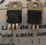
To prove it I did tested the BDW93C/94C I made a picture from the used parts.
Yes there is a minimal difference in the favour of these devices but they are only good max 30V rail voltage and you get about 30W 8Ohms or less.
To be honest someone has to be great ear to hear the difference between the BDW83C/84C and the BDW93C/94C
I made some mode in the circuit please let me know what do you think.
I took the feedback to the input only. I increased the input device voltage, they run on very very low voltage!
Probably I supposed to get read of the 100K resisters but I'm not sure.
Unfortunately I'm unable to run any simulation and to build it for a test in real life that would be a never ending something.
Would you be so kind please take a look and let me know your opinion
Thank you very much")
Again I do not want to make the amp sound better, with the sound I'm more than satisfied but if I could make it more stable under those extreme circumstances (0R22 emitter resisters, 250mA bias etc) that would be an extra
Greetings Gabor
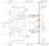
The first circuit the orig!
To prove it I did tested the BDW93C/94C I made a picture from the used parts.
Yes there is a minimal difference in the favour of these devices but they are only good max 30V rail voltage and you get about 30W 8Ohms or less.
To be honest someone has to be great ear to hear the difference between the BDW83C/84C and the BDW93C/94C
I made some mode in the circuit please let me know what do you think.
I took the feedback to the input only. I increased the input device voltage, they run on very very low voltage!
Probably I supposed to get read of the 100K resisters but I'm not sure.
Unfortunately I'm unable to run any simulation and to build it for a test in real life that would be a never ending something.
Would you be so kind please take a look and let me know your opinion
Thank you very much
Again I do not want to make the amp sound better, with the sound I'm more than satisfied but if I could make it more stable under those extreme circumstances (0R22 emitter resisters, 250mA bias etc) that would be an extra
Greetings Gabor
The first circuit the orig!
Attachments
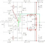
I made some mode in the circuit please let me know what do you think.
I took the feedback to the input only. I increased the input device voltage, they run on very very low voltage!
Probably I supposed to get read of the 100K resisters but I'm not sure.
Yes you did the right thing with increasing the bias for the input transistors.
About the 100K feedback resistors, you can remove them if you can get low DC at output. This topology has issue with bias stability. Those 100K resistors will help balance the symmetry. You can use slightly different value (e.g 92K on the top, 100K on the bottom) to zero DC offset.
In SSA, input cascode is used instead of extra feedback resistors.
You can lower the feedback resistance to lower distortion. In SSA amps, value around 1K is usually used. Stability is the price. Your amp in its current state is very stable (with such a high feedback resistance). With "stable" darlingtons such as 2N6284/87 you will have less problems lowering the feedback resistor.
I made some mode in the circuit please let me know what do you think.
I took the feedback to the input only. I increased the input device voltage, they run on very very low voltage!
Probably I supposed to get read of the 100K resisters but I'm not sure.
As connected in your mod the 100K resistors will no more provide
local feedback but they will still conduct a VA dependent current
from a base to the other , hence the iddle current variation
will stay exactly the same.
I think that the original designer didnt fully evaluate the consequences
of implementing such a biaising/local NFB loop using this scheme.
About the 100K feedback resistors, you can remove them if you can get low DC at output. This topology has issue with bias stability. Those 100K resistors will help balance the symmetry. You can use slightly different value (e.g 92K on the top, 100K on the bottom) to zero DC offset.
In SSA, input cascode is used instead of extra feedback resistors.
Thoses 100K resistors have no similarity with the SSA cascoded input,
the role is not the same.
In the SSA the cascode are used as voltage shifter to reduce the input
stage effective supply voltage.
Here , those 100K resistors are a local frequency independent local
feedback loop from power output to VAS input but since it is DC coupled
there will be a current flowing from output to the VAS bases and it is
obviously proportional to the supply voltage value , hence the VAS
current will increase dramaticaly with increasing VA wich will increase
the output transistors bias.
I think that the designer underestimated the effect of theses resistors.
You can lower the feedback resistance to lower distortion. In SSA amps, value around 1K is usually used. Stability is the price. Your amp in its current state is very stable (with such a high feedback resistance). With "stable" darlingtons such as 2N6284/87 you will have less problems lowering the feedback resistor.
The output devices are slow so it is counterproductive to reduce thoses
resistors values below 10K.
Hello
Thank you Jay and wahab!
My question now I increased the voltage on the input transistors do these setup work or I'll have problem to set up the right current on the BC550/560?
I'll keep the 100K resisters until I set up the amp after I will test it with out them to.
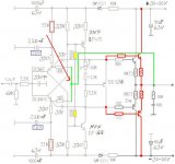
The reason I marked those yellow.
May be I will try to ad a extra feedback resister start with--10K and adjust it-- to decrease the feedback,
I have to test that to how will behave and how will influence the sound
All these mode I'll test one by one.
If any of these degrade the sound by a bit I will leave it out.
Again to me to improve the stability of the amp the main factor. With the sound I'm more than satisfied.
All do I have to admit I pushed the amp a bit to work in extreme condition with the following change from the original design
Originally was used one pair darlington with 0R33 emitter resisters
Now I reduced the emitter value which put more stress on the power transistors
If I parallel the power transistors and still keep the 0R22 emitters I think that will push it further (that was Anatech advise to keep the 0R22 even when I double the power transistors)
If I can get more power and more stability with one pair darlington (metal case TO3 transistor) by using min 250mA bias at 40V rail I'll keep the one pair darlington, the sound remain cleaner how I heard that before a bit less bass and dynamic.
At last test with one pair TIP the sound was excellent.
I couldn't test with BDW83C/84C because I didn't had from ST just made by ISC (garbage)
Now I get BDW83C/84C from ST, also I got MJ11### and these 2N#### Jay advised.
1)The big mistake I made last time I set up the bias to 250mA and felt sleep
2) The heatsink was to small
My friend used one pair BDW83/84 biased up to 400mA and used it over 10 years.
But he use large heatsink.. and 0R33 or 0R47 (I have to ask him)
After I heard the 0R22 emitter I do not want to go back to 0R33 or so
That mode act like a steroids on the sound!!
Fact
When I push the amp hard it produce 2X as much heat than other BJT amp with the same bias set up.
Heat sink, heat sink and more heat sink needed.
Ok those who interested these circuit how it is now it was not tested!
The orig circuit even with the 0R22 emitter at 100-150mA STABLE with the right cooling!
Please do not use the BF469/470 as a VAS that degrade the sound because only available from CDIL (Made in India)
MJE243/253 provided me great sound improvement over the BF-s..
I hope someone will give a try to these amp so I do not need to write about the sound quality anymore..
Greetings Gabor
Thank you Jay and wahab!
My question now I increased the voltage on the input transistors do these setup work or I'll have problem to set up the right current on the BC550/560?
I'll keep the 100K resisters until I set up the amp after I will test it with out them to.
The reason I marked those yellow.
May be I will try to ad a extra feedback resister start with--10K and adjust it-- to decrease the feedback,
I have to test that to how will behave and how will influence the sound
All these mode I'll test one by one.
If any of these degrade the sound by a bit I will leave it out.
Again to me to improve the stability of the amp the main factor. With the sound I'm more than satisfied.
All do I have to admit I pushed the amp a bit to work in extreme condition with the following change from the original design
Originally was used one pair darlington with 0R33 emitter resisters
Now I reduced the emitter value which put more stress on the power transistors
If I parallel the power transistors and still keep the 0R22 emitters I think that will push it further (that was Anatech advise to keep the 0R22 even when I double the power transistors)
If I can get more power and more stability with one pair darlington (metal case TO3 transistor) by using min 250mA bias at 40V rail I'll keep the one pair darlington, the sound remain cleaner how I heard that before a bit less bass and dynamic.
At last test with one pair TIP the sound was excellent.
I couldn't test with BDW83C/84C because I didn't had from ST just made by ISC (garbage)
Now I get BDW83C/84C from ST, also I got MJ11### and these 2N#### Jay advised.
1)The big mistake I made last time I set up the bias to 250mA and felt sleep
2) The heatsink was to small
My friend used one pair BDW83/84 biased up to 400mA and used it over 10 years.
But he use large heatsink.. and 0R33 or 0R47 (I have to ask him)
After I heard the 0R22 emitter I do not want to go back to 0R33 or so
That mode act like a steroids on the sound!!
Fact
When I push the amp hard it produce 2X as much heat than other BJT amp with the same bias set up.
Heat sink, heat sink and more heat sink needed.
Ok those who interested these circuit how it is now it was not tested!
The orig circuit even with the 0R22 emitter at 100-150mA STABLE with the right cooling!
Please do not use the BF469/470 as a VAS that degrade the sound because only available from CDIL (Made in India)
MJE243/253 provided me great sound improvement over the BF-s..
I hope someone will give a try to these amp so I do not need to write about the sound quality anymore..
Greetings Gabor
Attachments
You can lower the feedback resistance to lower distortion. In SSA amps, value around 1K is usually used. Stability is the price. Your amp in its current state is very stable (with such a high feedback resistance). With "stable" darlingtons such as 2N6284/87 you will have less problems lowering the feedback resistor.
I want to try to increase the feedback resisters not to decrease around 1K.
That would be another extreme mode here I think
Again the sound (including the distortion) after my ear is superior!
I can't run sim tests unfortunately..
Greetings Gabor
Attachments
Last edited:
Hello
wahab there are a few Sanken Audio transistor in MT-200 case (high power and fast) available.
SANKEN ELECTRIC : Power Transistors : General Purpose : NPN
But who knows what would happen if I would chose such a fast darlingtons, probably would start to oscillate???
Also the darlington structure not the same as the BDW or MJ.
Missing a resister and a diode.
For example these pair
http://www.sanken-ele.co.jp/en/prod/semicon/pdf/2sd2561e.pdf
I just posted these info because you wrote so many times my darlingtons are slow
Greetings Gabor
Thoses 100K resistors have no similarity with the SSA cascoded input, the role is not the same.
Yes they are different. But I have used both to solve the same issue.
In the SSA the cascode are used as voltage shifter to reduce the input
stage effective supply voltage.
Here , those 100K resistors are a local frequency independent local
feedback loop from power output to VAS input but since it is DC coupled
there will be a current flowing from output to the VAS bases and it is
obviously proportional to the supply voltage value , hence the VAS
current will increase dramaticaly with increasing VA wich will increase
the output transistors bias.
In the SSA, due to low FB resistance also (current feedback), the bias are very interdependent between input, VAS and output. Input bias is determined by the resistor supplying too low current (in the original schema) to the input emitter or feedback junction. This is affected by the high feedback current.
Very high feedback resistance is actually partially a solution but a compromise soundwise. AND also the input cascode is a compromise imo. These cascode and resistors are only solving electronics issue. Soundwise they are NOT NEEDED!
I think that the designer underestimated the effect of theses resistors..
Who knows? He put it there and it is not a common approach. Meaning that he wanted to solve something. I have used the same trick and it worked.
Despite many issues, this topology has something good. It is a good idea to experiment with newer darlingtons (but I couldn't find their spice models)
My question now I increased the voltage on the input transistors do these setup work or I'll have problem to set up the right current on the BC550/560?
I'll keep the 100K resisters until I set up the amp after I will test it with out them to.
The reason I marked those yellow.
If supply voltage is higher than +-35V BC546B/556B should be used instead.
If I parallel the power transistors and still keep the 0R22 emitters I think that will push it further (that was Anatech advise to keep the 0R22 even when I double the power transistors)
But he use large heatsink.. and 0R33 or 0R47 (I have to ask him)
After I heard the 0R22 emitter I do not want to go back to 0R33 or so
For better current sharing test the VBE of the parraleled darlingtons
before mounting them , use the ones displaying the closest values.
Input bias is determined by the resistor supplying too low current (in the original schema) to the input emitter or feedback junction.
And this bias current is dependent of the emitter currents wich
are varying with supply voltage variations in the case of this amp ,
hence there will be DC offset and VAS current variation by the same way.
Very high feedback resistance is actually partially a solution but a compromise soundwise.
10K seems close to optimum in this case but it is with the modded
schematic where input stage current are not VA dependent.
It slightly reduce the gain wich will remain at least 30db and wont
endanger stability.
Who knows? He put it there and it is not a common approach. Meaning that he wanted to solve something. I have used the same trick and it worked.
Despite many issues, this topology has something good. It is a good idea to experiment with newer darlingtons (but I couldn't find their spice models)
This amp design is influenced by the badly interpreted Matti Otala s
requirements of a 20KHZ OLG BW so his aim was to get an apparently 20Khz "open loop" gain by implementing a flat frequency feedback loop around the VAS and output stage , but by the same way he got a dramaticaly supply voltage dependent amplifier in respect of iddle current and DC offset ,
a misbehaviour magnified by the unregulated input stage currents.
As for Sanken s models , well , one has to wonder if they really want their
devices to be used by amateurs...
Last edited:
This amp design is influenced by the badly interpreted Matti Otala s
requirements of a 20KHZ OLG BW so his aim was to get an apparently 20Khz "open loop" gain by implementing a flat frequency feedback loop around the VAS and output stage , but by the same way he got a dramaticaly supply voltage dependent amplifier in respect of iddle current and DC offset ,
a misbehaviour magnified by the unregulated input stage currents.
Hmmm... what if it is all about smooth DC/AC operation versus good sound? There is a neverending debate about this "unnecessary" bandwidth or even about the benefit of current feedback approach. I myself, prefer a design that will sound (extremely) good, even if I have to find the right hfe for each transistors for the circuit to work.
As for Sanken s models , well , one has to wonder if they really want their
devices to be used by amateurs...
I have not yet understand the logic behind your statement. I think there is sufficient skill and knowledge from the amateurs to develop the model, if there is sufficient interest with the device (which is none I suppose?).
I have seen many amps using the device, they all have the same characteristics: very bad sound. Who was responsible for their designs?
Hmmm... what if it is all about smooth DC/AC operation versus good sound?
Dont know but the simulators says that not only perfs are no better
but DC operating conditions are largely degraded.
I have not yet understand the logic behind your statement. I think there is sufficient skill and knowledge from the amateurs to develop the model, if there is sufficient interest with the device (which is none I suppose?).
Extracting parameters using datasheets has limits , manufacturers
use real world extraction by computerized tools.
Moreover , a large batch of components is necessary to reduce
statistical errors.
Anyway , the most popular devices are the ones wich have
available models so it s quite counterproductive for Sanken
to not publish their devices models.
I have seen many amps using the device, they all have the same characteristics: very bad sound. Who was responsible for their designs?
Are you talking of the darlingtons used in this amp ?...
If supply voltage is higher than +-35V BC546B/556B should be used instead.
For better current sharing test the VBE of the parraleled darlingtons
before mounting them , use the ones displaying the closest values.
Hello
The 22K resister from both side will lower the voltage I think enough.. My rail voltage will be 40V...... At first I used 51V......
Right now with the 68K resisters I only get a couple volt, way under 10V on the input..
I think 10-15V min. need for the input... I can increase the 22K resister in case if it need to be..
I was worried about the current on the input not to over load the rest of the circuit (amplifier).
That is the million dollar question how to measure the VBE of the Darlingtons
At Budapest when someone (technician)did matched the darlingtons he used a special circuit at his work place to do so.
If you have advise about these please let us know.
Peoples like DX Carlos and others asked me how you match the Darlingtons..
Good question
If I parallel the darlington that increase the bass, dynamic share the load etc but if they not matched the mid range not crystal clear.
Greetings Gabor
Member
Joined 2009
Paid Member
[...]I know the sound of that amplifier and I was happy with [...] We some of us we need to learn to be satisfied with some good sounding amplifier and to settle down and enjoy the music . That is all about or not ?!
Of course I'm not totally retire from the DIY hobby but I want spend more time enjoy listening to the music . Greetings
I had to smile at this, because I feel the same way at times. Of my solid state amps, it's the first one I made that is still used everyday. I made others but I like the sound of the first one. I also rebuilt it with better parts and it is also based on an old and simple design that sounds great, RCA 1970 / AKSA. I am also trying to build less and enjoy the results more.
I did make a symmetric design, I called it "TGM5" and it is described in a thread around here somewhere. Like most symmetric VAS designs the VAS current is ill-defined and so the output bias is ill-defined. I used a lot of VAS emitter degeneration (as used by Bryston in their 2BST) which reduces VAS current instability. On top of that I used a simple Vbe multiplier circuit from Hagerman that is far less sensitive to any remaining VAS current variation. When combined these techniques produced stable bias. You can use the same solution.
I have to say that it's really nice to read your posts because of how you express your feelings about your project. I feel that I should build your amplifier !
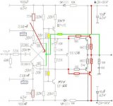
[…]This design as it sits runs out of current at some point. The outputs can not be properly driven, so the current drops as the voltage across the emitter resistor and E-B junction rises in the output stage.
Imagine a positive going waveform. [diagram post 98] As the E of Q1 goes high, following the base connection, the base of Q3 is also raised in voltage. Both the emitter of Q1 and Q3 are tied to their base voltages by Vbe. That means that the emitter of Q3 is related to the base of Q1 closely as the Vbe drops are similar (but not equal). As current flows through Q3 a voltage drop across P1 develops. This subtracts directly from the E-B voltage across Q3, so the base drive is reduced as the current increases. Now also look at the source of the current used to run Q3. That would be R5, a resistor. As your output voltage climbs, the current flowing through R5 is reduced - right when you need it the most! Use a CCS in those two locations (positive and negative). That will maintain the available current as your output voltage climbs. What you really need to do is somehow modulate the current into the Q1 emitter - Q3 base circuit so it increases with increasing input signal voltage. Positive feedback. You think it sounds clear now? Just you wait until these things are looked after.
Wow, this is interesting. You identify a potentially common weakness in the Diamond buffer topology and you have the solution - positive feedback. I think this is really a very interesting idea, perhaps so much that it could allow us to explore a no-feedback option - it deserves further follow-up. Maybe applicable to other output topologies.
Last edited:
Hello
The 22K resister from both side will lower the voltage I think enough.. My rail voltage will be 40V...... At first I used 51V......
Right now with the 68K resisters I only get a couple volt, way under 10V on the input..
I think 10-15V min. need for the input... I can increase the 22K resister in case if it need to be..
I was worried about the current on the input not to over load the rest of the circuit (amplifier).
Reducing the 68K to 22K will only increase the input stage current
by a 3 factor , hence completely changing the DC operating currents ,
so a lot components values should be changed in the same time.
As already said , the problem do not arise from theses resistors
values but with the fact that they see a voltage rail dependent
current , a problem adressed in the mod i posted where the input
stage current is still the same as in the original , hence all other components
have the same values apart from the VAS emitters resistors that are modded
such that the VAS current stay the same as in the original , about 5.5mA.
The input stage current is about 0.5mA while the VAS has 5.5mA , so using
for VAS devices that have a gain of 100 will yield no more than 50uA extracted
from the input stage to drive the VAS.
That is the million dollar question how to measure the VBE of the Darlingtons
At Budapest when someone (technician)did matched the darlingtons he used a special circuit at his work place to do so.
That s a good question.....
Given the integrated resistors a classical diode tester will be innefficient ,
the devices have to be measured at relatively high current mounted
as emitter followers.
The schematic below should be adequate if a regulated PSU is used.
The device dissipation is about 5W so it must be mounted on a heatpreader
with the voltmeter connected to base/emitter before powering since the Vbe
will deacrease with increased temperature.
Attachments
Last edited:
Hello
Thank you wahab!
So 10V regulated PSU needed..... Why has to be regulated?
I ask because I do not have at hand.
For mosfet matching I used to use my broken printer PSU. Of course is DC voltage.
That is 16V.
Usually I connect the PSU and I use stopper 45sec to 1min.
Depend what type of mosfet. JFet with 9V battery..
The 4.7R resisters has to around 20W?? otherwise with the resister temperature will change the measured V which would change by the warm up..
Can I use my 16V PSU here??
Anyway I will test the higher power darlingtons to, if they sound as good like the BDW-s or TIP very likely, probably will be enough.
When I paralleled the darlingtos even with out matching it had more advantage than disadvantage.
It degrade the mid-range a bit but the sound became more authoritative.
Actually I can't compare the sound of these amp to ether BJT amp or FET amp.
More like a good tube amp.
Has some warmth in it but the bass does not get rounded, a la many mosfet or tube amp, it remain precise. Deep and everything well separated. Sometimes I feel I can reach out to hold the hand of the singer etc.
Like he or she would be at front of me in my room.
Honestly very very hard even to imagine I can build a better sounding amplifier like these.
We compared these with serious amplifiers, not even came close either of them..
That time these amp was built from 1/4W cheap 5C resisters, cheap capacitors, magnet wires, cheap old Alps pot and 2 big 51 000 Mepco caps.
Here when I built with DALE resisters exotic parts my friend only could say the F word when he sat done and started to listen my favorite CD..
So to me these became more than "(just)" an amplifier. I feel my audio hunger will be satisfied or fulfilled if I succeed to put these amp together in a way to keep the orig sound with out any degradation and make it reliable and stable..
I do not go into the amp to change anything only I'll test the feedback mode... I keep the 68K resisters to.
Many thanks for your help!!!!
Greetings Gabor
Reducing the 68K to 22K will only increase the input stage current by a 3 factor , hence completely changing the DC operating currents , so a lot components values should be changed in the same time.
Yes, I have used 1mA of input bias. If I'm not mistaken it correlates with 42k resistor (40 or I think 45V supply). Feedback resistance around a quarter of the original. It worked okay, I just couldn't make it less than 500mA so I thought I need to compare it with other class-A amps, and I prefer SSA-HEXFET similar to F5.
Indeed, darlingtons have unique sound that some people like.
If I parallel the darlington that increase the bass, dynamic share the load etc but if they not matched the mid range not crystal clear.
Unfortunately paralleling doesn't solve the high bias requirements. Only damping. I wish I could share the currents to multiple output devices (to avoid thermal runaway)...
I have gold plated darlingtons from Motorola in TO-220. That's for my future project with this topology. No models for them, so I need first to use them in friendly topology to understand their behavior.
Are you talking of the darlingtons used in this amp ?
The Sankens. So where's the model?
- Home
- Amplifiers
- Solid State
- My first DIY amplifier 20 years a go