Hello
I did replace the emitter resisters with 0.22R . It since to me it has more bass now , more weight.
One think the bass now a bit softer , a like tube amps. The sound probably a bit slower.
When I replace the emitter resister the total bias goes up almost I get double bias .
So I have to readjust the bias .
Because of these do you think the front get enough bias??
I will go back with a higher emitter resister so I have to increase the total bias , let see what would happen .
On the signal emitter I measure only about 200mV that s enough ?
After couple track the amp get way to hot , I need to measure the bias again ! Thank God I put my hand on the heatsink. I think it was already 65-70C degree .
At the start I set up the bias 150mA when was cold may be to much . Or it possible when it warms up the bias goes up to ??
Do you think is a good idea to replace the 68K resisters with 47K to give a bit more voltage to the emitters of the signal transistors ?
I ask these because the amp was originally calculated to use 50V PS but with much lower bias.
Please let me know .
Thank you .
Greetings
Hello
Wahab thank you very much!
I already added the capacitor and I will ad the two transistor.
I have to check what type I have at home (I have a lot of) for the pin out.
I would have a question about my Darlington amplifier in case if you not to busy to answer.
It has thermal problem specially if I set up the bias 200-300mA.
The warmer the amp get the higher the bias goes and so on until self destruction.
Until now I compensated with over sized heatsink.
The sound of the amp is awesome!
Clear , neutral, huge bass, dynamic excellent.
So I do not want to mode the amp to degrade the sound but if I can make it more stable that would be great.
Now the amp use, was upgraded
JFet 2SJ74BL / 2SK170BL on the input
MJE243 / MJE253 VAS
2X TIP142/147 darlington (or BDW83C/84C I have to re test these transistor)
On the input 4.7uF NP Black Gate.
The emitter resistors are 0R22.
Many people laugh when they see darlingtons are used.
In case you think not wort to think about or to complex to make it stable I will leave it how it is.
The best sounding amp ever built..
I just thought I ask you in case you have time to take a look at the circuit please.")
In case if you do not have time I'm still grateful for all your help!!
Greetings Gabor
Wahab thank you very much!
I already added the capacitor and I will ad the two transistor.
I have to check what type I have at home (I have a lot of) for the pin out.
I would have a question about my Darlington amplifier in case if you not to busy to answer.
It has thermal problem specially if I set up the bias 200-300mA.
The warmer the amp get the higher the bias goes and so on until self destruction.
Until now I compensated with over sized heatsink.
The sound of the amp is awesome!
Clear , neutral, huge bass, dynamic excellent.
So I do not want to mode the amp to degrade the sound but if I can make it more stable that would be great.
Now the amp use, was upgraded
JFet 2SJ74BL / 2SK170BL on the input
MJE243 / MJE253 VAS
2X TIP142/147 darlington (or BDW83C/84C I have to re test these transistor)
On the input 4.7uF NP Black Gate.
The emitter resistors are 0R22.
Many people laugh when they see darlingtons are used.
In case you think not wort to think about or to complex to make it stable I will leave it how it is.
The best sounding amp ever built..
I just thought I ask you in case you have time to take a look at the circuit please.
In case if you do not have time I'm still grateful for all your help!!
Greetings Gabor
Attachments
I already added the capacitor and I will ad the two transistor.
I have to check what type I have at home (I have a lot of) for the pin out.
Anything will work , so spare your good parts...
It has thermal problem specially if I set up the bias 200-300mA.
The warmer the amp get the higher the bias goes and so on until self destruction.
Until now I compensated with over sized heatsink.
I assume that the BD136 is mounted on the heatsink, if not the case
what happens is logical.
The nominal 200mA bias is to be set only when the amp has warmed ,
so let the amp getting hot and set the bias.
Try this way , if it keeps going in thermal runaway then something
else is fishy , perhaps it oscillate .
If oscillations occur connect 100 to 220pF caps from base to collector
of the darlingtons.
The TIP darlingtons are not good performing devices , we can
summarize them as being some kind of TIP29/33 and TIP30/33
arranged as darlingtons , and overall they can be prone to
oscillations.
The BDW83/84 are the same devices but with european
naming scheme.....
Anything will work , so spare your good parts...
I assume that the BD136 is mounted on the heatsink, if not the case
what happens is logical.
The nominal 200mA bias is to be set only when the amp has warmed ,
so let the amp getting hot and set the bias.
Try this way , if it keeps going in thermal runaway then something
else is fishy , perhaps it oscillate .
If oscillations occur connect 100 to 220pF caps from base to collector
of the darlingtons.
The BDW83/84 are the same devices but with european
naming scheme.....
Hello
Thank you for the answer.
I used to set up the bias when the amp cold and keep check it until it warm up.
To be honest the amp was designed to run it about 30mA/ channel.
But it sound better if I increase the bias.
I don't know if is oscillate, to check that I would need scope.
I can't hear any strange sound...I know that not a proof the amp is not oscillate.
Yes BD136 is mounted on the same heatsink where the power transistors.
I will try the suggested capacitor in case I still have the problem.
Now the amp under rebuild because last time it gone up into flame. I did listen a CD (sounded so good I felt sleep). A few hour later I woke up the amp is burning! Thank God the Visaton woofer took the 40V, still good.
The heatsink was so warm I could not touch it.
Probably the heatsink was to small to???
Now I give 2 or 3 time larger. My friend run the amp 350mA bias over 10 years with one pair darlington until one channel started badly distort for some reason..
To me that mean the amp is stable with the originally designed transistors...
BC414C/416C input, BF469/470 driver, and BDW83C/84C
Also I will try ON semi MJ11015/16 darlington it has more power more rugged.
You know the amp sound so good I can't give it up!
To be honest I just wanted your opinion, I do not want to waste your time on these.
You helped me more than I ever can thank you!
Greetings Gabor
I used to set up the bias when the amp cold and keep check it until it warm up.
To be honest the amp was designed to run it about 30mA/ channel.
But it sound better if I increase the bias.
I don't know if is oscillate, to check that I would need scope.
I can't hear any strange sound...I know that not a proof the amp is not oscillate.
Yes BD136 is mounted on the same heatsink where the power transistors.
BC414C/416C input, BF469/470 driver, and BDW83C/84C
Also I will try ON semi MJ11015/16 darlington it has more power more rugged.
If you intend to rebuild this amp use 0.47R resistors as in your
schematic , it will help prevent thermal runaway if it s DC conditions
related.
That said , TIPs are not the best devices for amps along with the BDV64/65 ,
both rugged but notoriously slow , the BDW83/84 being of the same vein.
BDW93/94C are somewhat a little better but they are only 80W or so with
a TO220 case that do not allow for high power over long periods.
The MJ11015/16 should be better candidates if you already have a few.
What appear in simulations is that this amp is sensitive to the output devices
speed , the slower the output devices the less stable , the other transistors
having far less influence.
Unfortunately there are not cheap good quality power darlingtons ,
at least not known of me.
Old types include the MJ11015/16 , MJ2501/3001 or BDX66/67 , all being
quite average and overhelmingly outmatched by more recent products
notably Sankens.
I have another question
Can I use only 2PC capacitor in my amp power supply as efficient like 4PC CRC or CLC?
I see several good brand amp use only 2 large can cap in PS.
For your darlington amp 2 x 10000uF per channel should be enough
given the output power while the mosfet amp in this thread will also
be content with such capacitances.
If huge capacitances are needed then it likely means that the design
is weak and has poor power supply noise rejection.
The MJ11015/16 should be better candidates if you already have a few.
What appear in simulations is that this Darlington amp is sensitive to the output devices
speed , the slower the output devices the less stable , the other transistors
having far less influence.
For your darlington amp 2 x 10000uF per channel should be enough
given the output power while the mosfet amp in this thread will also
be content with such capacitances.
If huge capacitances are needed then it likely means that the design
is weak and has poor power supply noise rejection.
Hello Wahab
Thank you for the simulation.
Also thank you for the answer about the capacitors.
Greetings Gabor
latest posts moved to here from other thread
http://www.diyaudio.com/forums/soli...-designed-paul-kemble-naim-7.html#post3237654

moderation
http://www.diyaudio.com/forums/soli...-designed-paul-kemble-naim-7.html#post3237654
moderation
Hello
Wahab I did tested the BDW93c/94c it does sounded better than the 83/84 but I think because the 93C/94C was produced by ST. The 83/84 was produced by ISC.
Now I got some orig ST BDW83C/84C and I will use those.
They are more rugged devices. Also I ordered some TIP142/147 they aren't bad. I have a NP A40 amplifier with the same transistors.
Pass also advise as a replacement the MJ11015/16 from ON semi.
I have a few of them at home.
I will test them to.
Originally the amp used 0R33 Emitter resistors, I did increased those to 0R47 to protect the power transistors and make the amp more stable.
Yes it worked but it degrade the sound of the amp a lot.
That is why I tried out the 0R22 resistors and gave me a huge sound improvement.
Also Anatech advised that to.
Another problem the BF VAS transistors only available from India and sound awful. So I picked the MJE243/253 which gave me a lot of improvement to.
Only problem there is huge Hfe difference between the NPN & PNP device.
On the circuit there is no offset adjustment so I have to do that with the input JFet or transistor. I have to select (MATCH) them to get read of the offset.
Again to me these amplifier sound so good I could newer give it up on her until I feel no more (not much) improvement left and 100% stable.
Yes for a while I gave up because here in N America hard to find the same transistors than in Europe but slowly I learned they are available only marked different to the American market.
Greetings Gabor
Attachments
Wahab I did tested the BDW93c/94c it does sounded better than the 83/84 but I think because the 93C/94C was produced by ST. The 83/84 was produced by ISC.
Now I got some orig ST BDW83C/84C and I will use those.
They are more rugged devices. Also I ordered some TIP142/147 they aren't bad. I have a NP A40 amplifier with the same transistors.
Pass also advise as a replacement the MJ11015/16 from ON semi.
I have a few of them at home.
I will test them to.
Originally the amp used 0R33 Emitter resistors, I did increased those to 0R47 to protect the power transistors and make the amp more stable.
Yes it worked but it degrade the sound of the amp a lot.
That is why I tried out the 0R22 resistors and gave me a huge sound improvement.
Also Anatech advised that to.
BDW93/94 have higher frequency limit than the BDW83/84
but both pairs can have low and variable gains , hence there will be
some difference even among the same parts.
Another problem the BF VAS transistors only available from India and sound awful. So I picked the MJE243/253 which gave me a lot of improvement to.
Only problem there is huge Hfe difference between the NPN & PNP device.
On the circuit there is no offset adjustment so I have to do that with the input JFet or transistor. I have to select (MATCH) them to get read of the offset.
The 2SA1360/2SC3423 pair used in the mosfet project amp suit
perfecly the task as VAS and are way better than the MJE2XX or
even the BF4XX.
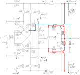
As for iddle current , this amp is sensitive to voltage supply variations
since there is biaising currents that are not regulated.
Particularly , the two 100K and 68K resistors (cercled in blue in the schematic
below ) will see variable currents with varying voltage , hence there will
be both quiescent current variation (the 100K influence mainly)
and output DC offset variation (the 68K mainly);
To adjust the DC output offset just use a resistor parraleled with
only one 68K resistor , the exact one depend of the offset polarity.
Start with a 4.7 meghom resistor and progressively reduce its value
to the next E12 steps , that is 4.3MR , 3.9MR and so on.
Attachments
The 2SA1360/2SC3423 pair used in the mosfet project amp suit
perfecly the task as VAS and are way better than the MJE2XX or
even the BF4XX.
As for iddle current , this amp is sensitive to voltage supply variations
since there is biaising currents that are not regulated.
Particularly , the two 100K and 68K resistors (cercled in blue in the schematic
below ) will see variable currents with varying voltage , hence there will
be both quiescent current variation (the 100K influence mainly)
and output DC offset variation (the 68K mainly);
To adjust the DC output offset just use a resistor parraleled with
only one 68K resistor , the exact one depend of the offset polarity.
Start with a 4.7 meghom resistor and progressively reduce its value
to the next E12 steps , that is 4.3MR , 3.9MR and so on.
Hello wahab
I will replace one of the 68K resistor with a 100K multi turn (20X) trimmer. I'll set up to 68K and from there I can go both way until I get read of the offset. After I measure the trimmer and I replace it with resistor.
Good idea to test those Toshiba parts for driver, I will do that.
These amplifier way to sensitive, even if I swap one or two parts I can hear it right away.
The MJE as a driver give solid and deep bass compare to the BF....
Can be because the BF produced in India or the speed difference between the two device >>>?
So easy to increase or decrease the sound quality of the amplifier hard to explain it.
One of the reason I do not give up on her. At the last 22-23 years I built and tested ### amplifiers and the best sound I heard it was these amp. Period.
Greetings Gabor
..... Can be because the BF produced in India or the speed difference between the two device ........>>>?
Hi Gabor,
Have you been able to use a BF made anywhere else ? Is there any difference ?
From what I know they only package prefabricated chips in India. There aren't any large fabs in India ( if any at all! ). The only (small!) one they had was burned down several years ago. They are currently planning to set up a new fab but with what's happening globally I wonder if it will see light of day.
So the chip itself was made somewhere else . In that case it is possible that it has just borderline performance (?) ( bought for cost reasons !) So does anyone know if we have more than one fab that makes the BF devices ?
The better solution would be to just use a device like the Japanese alternatives. And they are probably better devices than the BF irrespective of which fab makes the device. It would be interesting to use JFET's at the input though several changes might have to be made.
Question to Wahab. Instead of cascoding a JFET at the input to protect it from high votages can we get away with a zener in series with the resistive load to the supply ?
Question to Wahab. Instead of cascoding a JFET at the input to protect it from high votages can we get away with a zener in series with the resistive load to the supply ?
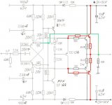
Yes and no....
This would work but not until the PS voltage has reached a couple volts
over the zener voltage so this reduce the supply voltage range accordingly.
Anyway ,in simulation Jfets do no better than Bjts , quite the contrary.
The main problem of this amp is in fact the point discussed above ,
that is , supply voltage highly dependent quiescent current.
For technical discussion , i post a variant where the 100K are suppressed
while 68K resistors are replaced by two resistors with a zener in the middle
to keep the emitters current stable.
In simulations , with the PS voltage increased from +-35V to +-40V ,
the original version has iddle current increasing from 124mA/pair to 180mA ,
that is almost 50% higher quiescent current for a meager 14% higher PSV.
In the modded version such a voltage variation yield 5% higher Iq , wich
is one order of magnitude better , while perfs are on par or even better.
Attachments
Last edited:
These amplifier way to sensitive, even if I swap one or two parts I can hear it right away.
The MJE as a driver give solid and deep bass compare to the BF....
Can be because the BF produced in India or the speed difference between the two device >>>?
So easy to increase or decrease the sound quality of the amplifier hard to explain it.
Due to the way it was designed there s a chain of dependencies between
the stages , first being the eventual low gain of the darlingtons that could
stress the VAS to the point that it can enter class B mode while
stressing the input stage to supply more current.
The 100K resistors do not only increase drasticaly the Iq sensitivity to supply
voltage variation , they also provide a local NFB loop from power output
to the VAS input , hence reducing global NFB to about 13db even at low
frequencies, wich will result in average damping factor , a behaviour magnified by the power transistors eventualy low gain.
That s a possible explanation to the variations in bass and sound quality you witnessed when swapping active parts.
I was toying with the idea of trying out the circuit with changes in the feedback. Since both the 100K and the 15K provided feedback I figured it would be OK to get rid of one of them. And as Wahab has done the 100K is the one than could go as the 15K determines overall gain.
For all the 'CFB' circuits that we have been seeing here , they are all actually only sensing output voltage and not current and feeding it back to the input device emitter which accepts it as a current. No matter how one looks at it or calls it , it does what one wants it to do !
A JFET at the input would see the feedback differently (?). Would that affect the sound ? Maybe we have to try it to find out.
Hello
In real life to me the JFet sounded better than BJT specially in the mid range area. More natural and detailed.
I used BC550C/560C because that was close to the orig used BC414C/416C the amp was designed.
For VAS I did tested device from other company like Philips & ST BD139/140 but those only good max 30V.
Also I purchased some NEC drivers but those where selected from Philips ECG catalog (on that time I didn't had computer access) may be they were not 100% complementary matched pairs. The amplifier work with those to but no improvement.....
ECG catalog sucks!
Now I tested ON MJ15030/31 (no improvement)and MJE243/253 the latest isn't bad transistor, gave me a lot of improvement.
But I get high offset (4V) because the difference between the PNP & NPN.
These MJE used at NAIM Chrome Bumper with the fast Saken transistor...
I think the speed of the VAS transistor is a major factor here. May be I'm wrong.
I would not go back to the BF type VAS. There is one Toshiba device I would like to test it but I have to order them 2SA940/2SC2073
I did tested the ISC (from India) Philipnes and ST Moroco BDW. ST sound way better! Also some of the ISC just blew up! Garbage..
I do like the mode of wahab at the last schematic
It would be great to test that (feedback only from the input transistors) that may be would make the amplifier less sensitive to the parts we use.
To be 100% honest the sound I heard at the last test incredible good.
I used only one pair TIP147/124 power darligton with 250mA bias at 40V rail voltage.
The bias was to high it was set up the amp was cold. I did listen 2 or 3 CD and I felt sleep.
I don't know if you ever felt that way the amp sound so good some type of peace comes on you.
I woke up because I heard some noise in my room, the 5W resister was burning between the 2PS caps. Also one of the power transistor burned and burn a huge hole on the PC board to.
The heatsink was so hot I couldn't touche it.
Now if I can get back the same sound and make the amp stable I will be more than happy with these amplifier for a life.
Is incredible how clean, detailed and deep bass it has. And the sound not as clinical or cold as some BJT amp. It has some warmness in the sound, probably from the darlington..
Greetings Gabor
Hello
I see you left out the 1000uF & 10uF caps.. Somebody gave me the same advise when he saw I use two large 51 000 Mepco caps in the PS.
It did degrade the sound drasticaly. The sound I got it was like tottal different amp. It become like a cheap old tube amp..
May be with that mode you done it will be different, I'm not sure.
I wouln't leave out those caps after that test I had done.
I just want to warn if someone test the amp, please pay att. about that..
Test it with caps and with out to.
Greetings Gabor
Hello
About the size of the decoupling I do not argue because I only used 1000uF an the 10uF how the circuit was designed.
All I know I removed the decoupling caps and I didn't recognized the sound of the amp!
I have some 470uF Cerafine, one day I'll test those instead the 1000uF Nichicon KZ & Silmic..
I always give a try to the 100nF but sometimes better just to use just the electrolytic, depend on the quality of both capacitor.
To decide about I usually do A-B test...
Greetings Gabor
Hello
If someone would like give a try to these amp these guy has BDW83C/84C made by ST for a $1/piece.
Darlington Power Transistors PNP 100V 15A BDW84C | eBay
That a steal..
You can also use TIP142/147 but only from ST...
You will not regret to test these amp I guaranty that. I hardly advise use speakers protection.
My Visaton mid-woofer survived the 40V 250mA or more.. You may not be so lucky.
Next time I set up the bias when the amp warm and I use some good quality speaker protection. It was my fault to set up the bias 250mA, the heat-sink was under sized and I felt sleep.
Greetings Gabor
- Home
- Amplifiers
- Solid State
- My first DIY amplifier 20 years a go