Hi Digit
Yes you right I got things wrong as I said already wonder why there is 3 question marks about silly number posted.
Al I wanted to say is 52 V swing on a 1 KHz sine even on 10 homs pure resistive load will mean that F5 will be plenty loud when plaiing music.
Could you please skip past the Rut of the Mean Square and move along.
Me remember posting apolologies for error of my ways some where else as well.
I also suffered 2 full Bon Iovy sides back to back
is it not punishment enough?
I had now the 2 channels of Cascode F5 running for a few days
Recap +26.017 -26.022 V rails 2.8 A on 2 parallel FQA12P20 FQP19N20
Parallel J fets (might as well try this while there) no current limiting.
I am liking it a lot my own personal impressions a bit more micro detail and a bit smoother Hi range (maybe due to less third harmonics) compared to exactly the same components transplanted on a cascoded board.
Her impressions;
"It sound even beter than before I could not believe it could have but it does"
This while plaiing Buddha Bar 4 track 10 Nikodemus / Desert Dancer.
IMO a very rare uncompressed recording if compared to moodern stuff that the F5 (me) does not like.
So I am really happy big big tanke thee Nelson Pass.
I think that it is going to stay there for a while I will need a much beter pre amplifier to make same more improvements and then be able to see if I can feel any difference.
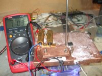
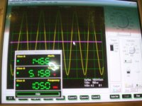
1and 2 themperature of metal tad on FQP19N20
3 offset
The sinks at 43 C just waiting for By amp or balanced
Recap +26.017 -26.022 V rails 2.8 A on 2 parallel FQA12P20 FQP19N20
Parallel J fets (might as well try this while there) no current limiting.
I am liking it a lot my own personal impressions a bit more micro detail and a bit smoother Hi range (maybe due to less third harmonics) compared to exactly the same components transplanted on a cascoded board.
Her impressions;
"It sound even beter than before I could not believe it could have but it does"
This while plaiing Buddha Bar 4 track 10 Nikodemus / Desert Dancer.
IMO a very rare uncompressed recording if compared to moodern stuff that the F5 (me) does not like.
So I am really happy big big tanke thee Nelson Pass.
I think that it is going to stay there for a while I will need a much beter pre amplifier to make same more improvements and then be able to see if I can feel any difference.
1and 2 themperature of metal tad on FQP19N20
3 offset
The sinks at 43 C just waiting for By amp or balanced
Attachments


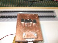
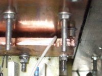
 Close ups
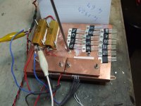
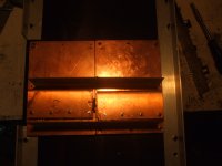
Clamp with cooper bar normal screw will strip tread
Thermistor/ Thermistors thin white twisted pair drill to fit as close to DUT
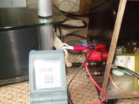
Can you see the digital thermometer same one one would use for Sunday roast (£15.99)
Dont need precision Just consistency
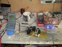
The 317 and mosfet fan speed controler and many other functions Board
If you think that it looks like the set up is different all the time You are quite right It tock a while to get things Just rigt
Attachments
Last edited:
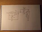
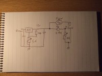
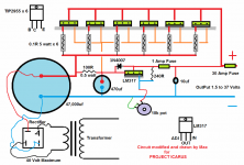
SCH of the test rig.
IF you need a regulated 24 V suply there are many out there
see picture for a pointer
I use similar with 3055 transistor
If you use more than 1A LM317 need same help
Link to Nelson Pass Article
http://www.passdiy.com/pdf/mos.pdf
As long as you mesure VGS at same point for example when temperature reach 50C after the third oscillation around the set point for all mosfets
you shuld get prety close results.
If you realy need precision a proper PID themperature controler is needed
Those can cost from around £300 and upward
Even beter than PID (proportional Integral and Differential Bands)
you can get new FUZY logic ones.
A PT100 or thermocuple is needed as sensor.
They normaly have 4 to 20 mA outputs that can be converted to controll the Mosfet gate voltagge.
But if you realy go that far get a proper Curve tracer and save yourself loads of trubles
Papa Pass article is good enoug for matching.
This is where he mention the efects of themperature.
Quote From Practical mosfet testing for Audio Nelson Pass
Measuring Vgs
The Vgs is temperature dependent, which means that the
parts tested should all start out at the same temperature,
usually room temperature (I mention this because at Pass
Labs we don’t heat our inventory area much in the winter,
and we have to let the devices sit in the test area to warm
up to room temperature).Also, as you run the test, you must be aware that you are
heating the devices both by running some current and
voltage through them, and also by touching them, and
the Vgs will alter with temperature. Ideally, you test the
devices under conditions identical to the intended use, and
this means mounting the devices in thermal contact with a
heat sink of the appropriate temperature and allowing for
the temperature to settle.
End Quote
By using 50 C and letting the mosfets to rest on the plate while you mesure one the efects of ambient temperature are reduced.
Warm up your mosfet to about 50 C
Set P1 so the A meater reads the current of your choice (2A)
and take reading of Voltagge between Gate and source
Group Mosfets togheter by VGS
take reading again at different current (1.3)
and repeat VGS mesurament
Group togheter again
Use the best matching you can get
Attachments
Mr. BkSabath...
The vdrop you found earlier with the chokes is meaningless. If you do the math you will see that the power out will drop a small %. HALF power is 3dB. In that perspective you see that it doesn't matter...
Also you have to look at your ripple under load, in case you were not.
The chokes are a good thing.
I think you said you WERE using a cascode front end to handle the higher B+??
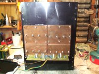
I am a little puzzled why you decided to make a separate central power supply and not
two supplies one with each amp? Among the things needed with a central supply (if that is what I am seeing?) are local caps out at the amp... Seems to me that this is a false economy compared to having two power supplies, due to the added cost of the central chassis, the labor involved with that, and the extra caps out at the amp modules. No?
EDIT: in the scope trace you show most recently, you show two square waves - the one above shows overshoot. Imo the amp should not show overshoot. That is the blip on the start of the square wave. However this can be magnified by improperly set up scope probes as well as other things. It is best to look at the calibrator on the scope with the scope probe and then adjust the little trimmer that is usually found on the probe for least overshoot first - or at least be certain that the squarewave on the scope is clean first (some scopes have an internal trim adjust too, and there may or may not be one on the probe).
However your arrangement certainly looks impressive...
_-_-bear
The vdrop you found earlier with the chokes is meaningless. If you do the math you will see that the power out will drop a small %. HALF power is 3dB. In that perspective you see that it doesn't matter...
Also you have to look at your ripple under load, in case you were not.
The chokes are a good thing.
I think you said you WERE using a cascode front end to handle the higher B+??
I am a little puzzled why you decided to make a separate central power supply and not
two supplies one with each amp? Among the things needed with a central supply (if that is what I am seeing?) are local caps out at the amp... Seems to me that this is a false economy compared to having two power supplies, due to the added cost of the central chassis, the labor involved with that, and the extra caps out at the amp modules. No?
EDIT: in the scope trace you show most recently, you show two square waves - the one above shows overshoot. Imo the amp should not show overshoot. That is the blip on the start of the square wave. However this can be magnified by improperly set up scope probes as well as other things. It is best to look at the calibrator on the scope with the scope probe and then adjust the little trimmer that is usually found on the probe for least overshoot first - or at least be certain that the squarewave on the scope is clean first (some scopes have an internal trim adjust too, and there may or may not be one on the probe).
However your arrangement certainly looks impressive...
_-_-bear
Last edited:
Hi Bear
Tanks for posting especialy the bit about scope calibration
I am fairly new at this and you comments ar much apreciated.
My F5 is wery much work of love in progress especialy as we are all waiting for the Turbo version.
Yes loads of work but this is the part I like / need most
At the moment is using the cascode as posted By Nelson on 2 paralel Jfets and 2 Parralel Mosfets for each rail.
It did sound a bit beter than the stock (my subjective impression) and has been up and running for few months now.
I was going to go back and rivisit this part of the design but first I need a decent Preamplifier and RIAA front end (I am working on those at the moment)
I have a separate suply as this keep trafo away from from the Mosfets
the small lenght of cable helps again with a small drop in riple
Eventualy the 2 mono blocks may be moved near the speakers so this cable will be longher
Just a question of where to put things, keep the BOSS hapy and dealing with room logistic and abboundance of mains sokets.
Yess there is extra cost for the separate enclosure but I made that up by building the separe enclosures for the amplifiers out of practicaly nothing exept the heath sinks.
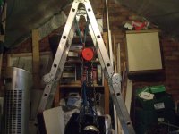
I started up with a single box dimentions where abaut 320X400X550 WDH I had to use a block and tacle to get the thing downstairs from the Loft.
So 3 separate boxes are much easier to move.
The extra caps just add more capacitance and one more CRC stage so it is now CRCLC
There is a total of 15 X 10mU on each of the suply rails.
About the chokes yes god thing to have again I will need to look at those, as for start the cooper is 2 thick and a pain to wind up (I got that by the Kilo) next time I will use 1/2 of the wire diameter and double the lenght possibly even wind the 2 wires togheter.
If I may it does sound impressive as well
Tanks for posting especialy the bit about scope calibration
I am fairly new at this and you comments ar much apreciated.
My F5 is wery much work of love in progress especialy as we are all waiting for the Turbo version.
Yes loads of work but this is the part I like / need most
At the moment is using the cascode as posted By Nelson on 2 paralel Jfets and 2 Parralel Mosfets for each rail.
It did sound a bit beter than the stock (my subjective impression) and has been up and running for few months now.
I was going to go back and rivisit this part of the design but first I need a decent Preamplifier and RIAA front end (I am working on those at the moment)
I have a separate suply as this keep trafo away from from the Mosfets
the small lenght of cable helps again with a small drop in riple
Eventualy the 2 mono blocks may be moved near the speakers so this cable will be longher
Just a question of where to put things, keep the BOSS hapy and dealing with room logistic and abboundance of mains sokets.
Yess there is extra cost for the separate enclosure but I made that up by building the separe enclosures for the amplifiers out of practicaly nothing exept the heath sinks.
I started up with a single box dimentions where abaut 320X400X550 WDH I had to use a block and tacle to get the thing downstairs from the Loft.
So 3 separate boxes are much easier to move.
The extra caps just add more capacitance and one more CRC stage so it is now CRCLC
There is a total of 15 X 10mU on each of the suply rails.
About the chokes yes god thing to have again I will need to look at those, as for start the cooper is 2 thick and a pain to wind up (I got that by the Kilo) next time I will use 1/2 of the wire diameter and double the lenght possibly even wind the 2 wires togheter.
If I may it does sound impressive as well
Fyi, keeping the xfrmr away from the mosfets (actually the input would be more likely to pick up hum) isn't really very much of an issue... it could be but in practice rarely makes any difference.
You do have power caps in each of your amplifier boxes??
_-_-bear
if you use half the diameter wire (thinner wire) and twice the length, ur DCR will increase and you will get more Vdrop, but lower ripple... FYI.
You do have power caps in each of your amplifier boxes??
_-_-bear
if you use half the diameter wire (thinner wire) and twice the length, ur DCR will increase and you will get more Vdrop, but lower ripple... FYI.
Last edited:
Yes Just 100.000 u at the moment
Will duble that when I get balanced.
Still separate box solved the problem of moving the beast.
More V drop Is not a problem as Trafos got tap to 20 and 24 V ac
So plenty of head room as I am not pulling more than 16 V at mental listening levels
Will duble that when I get balanced.
Still separate box solved the problem of moving the beast.
More V drop Is not a problem as Trafos got tap to 20 and 24 V ac
So plenty of head room as I am not pulling more than 16 V at mental listening levels
So, here's a question... where is ground?
if it is on the chassis, then it is Vdrop above real ground, if ground is in the PS chassis...
the reason I ask is that IF the ground on the chassis of the amp is N volts above the PS chassis ground due to the cable length, then when you plug in an RCA to the input of the amp, the ground on the RCA cable and the ground on the amp chassis are at two different voltages! Current could flow, which would not be good...
...suggest checking with a DC and also for yuks an AC voltmeter between the shield of ur RCA interconnect (disconnected from the amp) and the RCA jack shield.
Let us know if you find any differential?
You can also test across the Ground wire going back to the PS from the amp chassis, and see if there is any voltage there (with the amp on).
_-_-bear
Ground is on a 15 mill cooper plate with 3 separate bolts for signal suply raw suply filtered.
Screen is conected only on the preamp end.
Of course there is a volt drop any cable has a finite resistance.
I am using 2 cores of 2.5mm square cable so with the curent 1 meter of cable is not much but it is there and realy bugging me
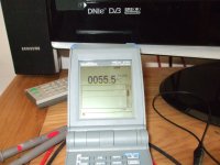
the second picture is a mesure of the DC if I remember the meter was there for a couple of minutes so a bit of difference between min and max
Picture 3 is a pt 100 sitting on the top of one of the 4 Mosfets after a couple of hours of prety loud prety musik.
Yes if your heat sink get to hot play lauder and the will cool down
I got a DC filter on the mains 8 12.000 u and a bridge rectifier just in case I am putting DC back in to the mains
PS I supose I could take a reding of the volt drop across the cable the meter is prety good.
Screen is conected only on the preamp end.
Of course there is a volt drop any cable has a finite resistance.
I am using 2 cores of 2.5mm square cable so with the curent 1 meter of cable is not much but it is there and realy bugging me
the second picture is a mesure of the DC if I remember the meter was there for a couple of minutes so a bit of difference between min and max
Picture 3 is a pt 100 sitting on the top of one of the 4 Mosfets after a couple of hours of prety loud prety musik.
Yes if your heat sink get to hot play lauder and the will cool down
I got a DC filter on the mains 8 12.000 u and a bridge rectifier just in case I am putting DC back in to the mains
PS I supose I could take a reding of the volt drop across the cable the meter is prety good.
Attachments

Last edited:

Seems like 55deg C for the Mosfets is too hot.
How hot is the copper that they are attached to?
How hot is the aluminum fins?
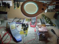
Got a clear picture of the heatsink - not too close up? Would like to see the overall arrangement... wide shot.
It's a class A amp, if properly biased and the temp should be pretty constant playing music or not...
_-_-bear
EDIT: wait a sec, we work in F around here... 55deg C would be around 110F? Not too awful bad...
If you can keep ur hand or fingers on it for any length of time, then I guess it passes... but check the temps as suggested, that will show heat transfer.
How hot is the copper that they are attached to?
How hot is the aluminum fins?
Got a clear picture of the heatsink - not too close up? Would like to see the overall arrangement... wide shot.
It's a class A amp, if properly biased and the temp should be pretty constant playing music or not...
_-_-bear
EDIT: wait a sec, we work in F around here... 55deg C would be around 110F? Not too awful bad...
If you can keep ur hand or fingers on it for any length of time, then I guess it passes... but check the temps as suggested, that will show heat transfer.
Last edited:
Top of mosfet is hot then a bit of resistance in heat transfer and therefore a themperature differential and a bit of resistance fromcooper to sink again bit of themperature differential.
sinks at about 42C on good day Just waiting for summer to see.
I am not going to do math while public library is open and get a post so somebody can just keep up his avverage.
To put it another way what is the temperature of your window easy to do and prove.
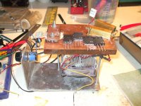
Fair wiew of F5 turborbo ready sink?
Why 3 boxes have alook at safeish way to move the thing
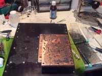
Spreaders ready to go just special black goop
And work in progress what the 2 croseed over resistor are doing there not just holding the board togheter
(this is quite a long title for a picture so lets put a bit under extra set of brakets as is often done) (one day I may get a balanced pre juppie!)
And it only works if it is shiny
sinks at about 42C on good day Just waiting for summer to see.
I am not going to do math while public library is open and get a post so somebody can just keep up his avverage.
To put it another way what is the temperature of your window easy to do and prove.
Fair wiew of F5 turborbo ready sink?
Why 3 boxes have alook at safeish way to move the thing
Spreaders ready to go just special black goop
And work in progress what the 2 croseed over resistor are doing there not just holding the board togheter
(this is quite a long title for a picture so lets put a bit under extra set of brakets as is often done) (one day I may get a balanced pre juppie!)
And it only works if it is shiny
Attachments
Last edited:
Assuming the surface of the copper and the heatsink is FLAT and you use some sort of appropriate heat transfer goo, the temp of the copper and the heatsink in the rear where they join ought to be within a very few degrees of each other.
I'd not worry about who says what about your math... irrelevant.
_-_-bear
I'd not worry about who says what about your math... irrelevant.
_-_-bear
Hi bear the surface is flat I got the sink machined flat before the anodising so no problem there.
The cooper was flat as it was machined as well.
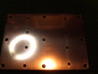
Then about 10 hours of hand polishing on a granite surface which was also Flat
Start with 160 paper and al the way to 600 then buffing and at the end in place spreader on sink paint scrach remover or Bi carb of soda.
Repeat for each spreader as polishing is done in place on the sink.
The crapy last picture is crappy because the camera dont realy like the flash camming off a mirror
I was happy when the spreaders stuck to the sinks as if magnetised sometink to do whith the vacum formed in between the 2
The special goo is graphite based pricey but I don't think there is better.
Unless one want to use diamond paste.
Snag with it is that it is conductive so ok on spreaders but not on mosfets.
Each plate is fitted with 9 M6 bolts on elicoil inserts (much more torque than straight aluminium) heath does the rest as thing expand a bit
The mosfets clamped with nice copper bar with M4 captive bolts (head burried in the inside on the spreaders) much more pressure then simple screw and washer.
Which is just what the Kerafoll 86/83 need as the thermall resistance drop with pressure.
I refuse to worry much with the mat or spelling on a diy site.
And it gives the professors that newer built a thing in their life a chance to gogle up things and feel like a somebody just because they post on avverage 10.81 post each day.
Yuppie I going to get the moderators to spank me again
I got the ignore button superglued on that one.
Sound is realy good wit 2.6 A bias I find them realy punci.
And Papa said "they sound beter with hier bias"
Kik Drums went from pum pum with a 120W amp I had before to realy nice Tum Tum this most probably due to the exuberant capacitance on the suply.
The Polk LSi15 are not the easist thing to drive and to keep in controll
I tried the integrated Krell and was not happy at all Papa design is realy mind bogling goooood.
The rest is just pure bliss and I can ear details that where not there before.
Altrought same poor especilay live recordings do not sound that good (and this is where same fine tuning will most definetley make the difference)
Sound stage and this is part of the Polk magic is realy good and way out tridimentionaly from the limits of my narow room.
As triing different things I had a quick stab with the Toshibas pairs
On quick impressions the Farchilds have much more dinamics and punch.
I find myself pushing the volume up quite a lot as listening fatigue is totaly gone.
They deserve a realy good Pre and Phono stage and I am working on those.
Once I have a decent source the real fun bigin with and I will start to tweack things.
But then the Turbo version is on its way....
One thing that realy bugs me is that I have never eard a pair of original Pass Labs F5 or another build be nice to be able to compare the different sound over a few pints.
- Status
- This old topic is closed. If you want to reopen this topic, contact a moderator using the "Report Post" button.
- Home
- Amplifiers
- Pass Labs
- My F5