Of course that is the plan
My way to give sometink back and big tanks to Nelson Pass for making this trip possible
Altrought nothing new just standard F5 whith no over current (Q6 and Q5)
I have posted the controll circuit SCH already (PS working fine up to now)
I supose it can be posted again maybe that is the only original bit but far to symple a thing to claim any merit.
The DC trap I got from ESP pages and post from Papa and uncle Zen
Zen
Maybe the only change worth reporting was the value of the source resistors
dropped to 0.22 R as far more current and Voltagge than stock
Got a few things to do so you may ask yourself why 4 terminals for speakers and second sets of bolts on heat spreaders.
Eventualy (2 60 hours week at work )is going to be by amping the Polks maybe a week worth of bliss on that configuration.
and report back
I would realy try to push the heat sink/ heath spreaders a bit, they where working fine with the hi voltagge hi bias so as long as the junctions/body of the mosfet (8 for this configuration) is below 65/70C it should be fine.
It may justify the hard work on the heath spreaders and clamps.
A second week with the Fairchild (Papa said less distortion from those)
and eventualy is just disconect one side of the 10 R and X connect them to the boards sitting under it and go ballanced.
Balanced (4 Xcurrent and beter tune in) against By amp is going to be realy interesting
I seen a J fet phase splitter circuit on Linear Audio that is worth investigating while I wait for the new Preamp.
When this is done and got enoug stashed away is going to be back to the friendly machine shop to get same 15mm aluminium machined for the final cabinets (no much change shape wise I just like to get rid off real ugly wood and alu L section I am using at the moment
My way to give sometink back and big tanks to Nelson Pass for making this trip possible
Altrought nothing new just standard F5 whith no over current (Q6 and Q5)
I have posted the controll circuit SCH already (PS working fine up to now)
I supose it can be posted again maybe that is the only original bit but far to symple a thing to claim any merit.
The DC trap I got from ESP pages and post from Papa and uncle
ZenMaybe the only change worth reporting was the value of the source resistors
dropped to 0.22 R as far more current and Voltagge than stock
Got a few things to do so you may ask yourself why 4 terminals for speakers and second sets of bolts on heat spreaders.
Eventualy (2 60 hours week at work )is going to be by amping the Polks maybe a week worth of bliss on that configuration.
and report back
I would realy try to push the heat sink/ heath spreaders a bit, they where working fine with the hi voltagge hi bias so as long as the junctions/body of the mosfet (8 for this configuration) is below 65/70C it should be fine.
It may justify the hard work on the heath spreaders and clamps.
A second week with the Fairchild (Papa said less distortion from those)
and eventualy is just disconect one side of the 10 R and X connect them to the boards sitting under it and go ballanced.
Balanced (4 Xcurrent and beter tune in) against By amp is going to be realy interesting
I seen a J fet phase splitter circuit on Linear Audio that is worth investigating while I wait for the new Preamp.
When this is done and got enoug stashed away is going to be back to the friendly machine shop to get same 15mm aluminium machined for the final cabinets (no much change shape wise I just like to get rid off real ugly wood and alu L section I am using at the moment
Attachments
Whit Tarragon
I respect your opinion you are welcome to stick with it.
altrought I resent the Cheap Shot remark Nothing Cheap there believe me for now
I will stick to mine and still refrain from further posting the reasons I got mine.
Can we live this to that?
Please
I respect your opinion you are welcome to stick with it.
altrought I resent the Cheap Shot remark Nothing Cheap there believe me for now
I will stick to mine and still refrain from further posting the reasons I got mine.
Can we live this to that?
Please
Last edited:
Altrought nothing new just standard F5 whith no over current (Q6 and Q5)
Maybe the only change worth reporting was the value of the source resistors
dropped to 0.22 R as far more current and Voltagge than stock
Can you tell us (again, sorry....) what current and voltage you are running? What does that work to, in terms of output (watts/channel)?
(I thought you might have been running either paralleled MOSFETs/some cascode arrangement....no?)
Hi Ken
Yess parralel Toshibas (8 for stereo F5 needed Just to keep things simple)
Quote from post 1>
Recap
26 V rails
Currently biased at 3.5 A
I have a doggy 1000VA transformer
230 V primary
0 20 24 V
0 20 24 V secondary
I am using the 20 V taps at present
150 mU capacitors banks in CRCLC
I have split the last 50 mU between the two channels for total 200 mU
I am using 10mU 63 V capacitors beter quality at 2 times the price on their way.
Still same all same all But Just 2 mono blocks with separate psu and no dogy transformer to spoil the plessure.
To get same objective results I will try to change only one thing at each time hopefuly this will help others avoiding the same mistakes.
This at time is a bit unpratical so my apolologies but from post one
New Aux controll Just 24 V LM317 and a 1 transistor Flip Flop + a one transistor timer
for on off function and soft start
Added DC trap with maybe to many 6.8V 12mU caps back to back and bridge diode.
new PCB for first CRC to 2.2 od cooper solid wire 1 KG each Yes mistake here proper coil should have been made up with 1.6 od and abaut 150 ft in lenght.
Yours truly bougth the cooper wire by the Kilo (£14 a kilo)
Tanks Zen for calculator (let me know if you did not see that and the folowing post I am at work on a crapy 386 like thing but will post link when I can )
And I have changed the last bank of 50mU with the new Rifa.
Not a chance to realy listen to it (56 hours week at woork) but will do
Yes paralels at 26 3.5 A and 32 3A
Wat out so far mesured to 4 homs speaker therminals 12.8 V peack 12.8 X 12.8 /4+ W40.96
Okydokeyduck
Back from work on proper PC
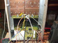
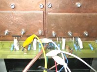
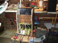
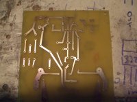
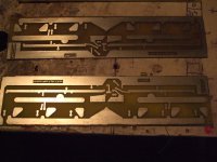
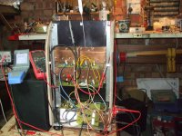
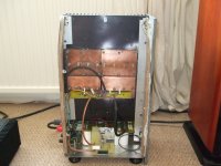
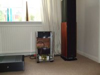
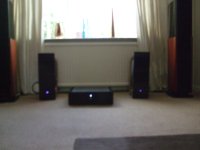
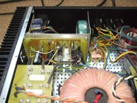
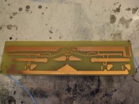
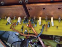
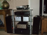
1 2 and 3 Pictures beter than million words The F5 mono block up and running picture 2 yes parallels no current limiter nothing fussy just bliss to the ears
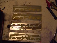
4 new batch of PCB for Fairchild trials.
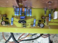
Close up of same let me know if you need the proper drawing it’s free.
And yes-got room for triplets.
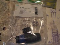
Protection NTE7100 board
I got same 4 pole 30A connectors for the 15-foot cables from PSU
Did not feel like running same Ac on same cables to the NTE pin for power down speaker disconnect so a 100 K pot just to get the right voltage and relay open if Rail get below 22 V
No speaker thump (F5 got very little of it so do not worry)
And the connectors 30 A rated and £3 maybe 4 yes I know I can get lemos at 10 time the price but why bother after all for best un-compromised performance the cables soldered straight on the PCB with no breaks would perform better but be a bit less practical
http://www.diyaudio.com/forums/swap-meet/182480-holco-mfr-15ppm-2w-sale.html
Back from work on proper PC
1 2 and 3 Pictures beter than million words The F5 mono block up and running picture 2 yes parallels no current limiter nothing fussy just bliss to the ears
4 new batch of PCB for Fairchild trials.
Close up of same let me know if you need the proper drawing it’s free.
And yes-got room for triplets.
Protection NTE7100 board
I got same 4 pole 30A connectors for the 15-foot cables from PSU
Did not feel like running same Ac on same cables to the NTE pin for power down speaker disconnect so a 100 K pot just to get the right voltage and relay open if Rail get below 22 V
No speaker thump (F5 got very little of it so do not worry)
And the connectors 30 A rated and £3 maybe 4 yes I know I can get lemos at 10 time the price but why bother after all for best un-compromised performance the cables soldered straight on the PCB with no breaks would perform better but be a bit less practical
http://www.diyaudio.com/forums/swap-meet/182480-holco-mfr-15ppm-2w-sale.html
Attachments
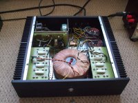
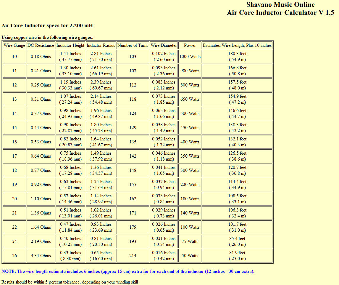
A bit about the inductors
I got the wrong wire and 1 a real pain to make pretty 2 it should have been about 150 foot long (2.2 target)
But I also have 2.5 mV of ripple and I am quite happy with that same of it from doggy pre and 15 foot cables.
No thermistors on the ground the signal in cable is connected to ground on the preamplifier and that is that
Inductor Designer / Calculator
Courtesy of Zen Mod post 773 Papa amp pictures tread
wires.co.uk : Enamelled Copper Wire
They sell wire by the Kilo at about £14 for the posh stuff
And nice handy table posted by CeeVee on post 774 Papa amps tread
http://www.diyaudio.com/forums/atta...pictures-your-diy-pass-amplifier-air-core.jpg
http://www.diyaudio.com/forums/swap-meet/182480-holco-mfr-15ppm-2w-sale.html
A bit about the inductors
are you talking about chokes ?
I thought they could only be used with tube amps, and no good for higher current
or maybe it works because of the lower voltage
another thing with chokes, they seem to be exstremely sensitive to bigger supply caps
or maybe its like above, and I have misunderstood something
You may call them the right name I don't know
Just a kilo of copper wound up as in the picture just before the cables get out of the PSU and reach the last bunch of C in the "mono" Blocks
I supose that 2.2 mm diameter can do same preaty enough current
My mistake was to get 2 kilos of it while I probabably should have used 4 Kilos
Remind me of a comic book Flower shoop selling flowers by the kilo so me think is quite funny any way they are there and not doing any arm at least riplevise.
But now that you mention it I may shorth them out and have a listen.
Last edited:
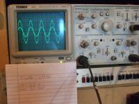
Well it looks like I need a couple of fans after all
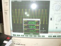
The F5 playing along 20V peak 1Khz
Same set up but poor pictures to enclose THD 0.098
Will have to get back to that...
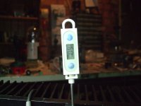
Same temperature measurement in the mean time
Top of the worst mosfet case 71.3 C
Copper heat spreaders 63.3
Heath sink 53.7
Worst possible positions (I will be only cheating myself)
I am quite happy with such a small difference between the 3
The effort invested in to the thermal coupling paid off.
I had a mosfet running a bit hotter but a "couple" more turns on the securing nuts cured that
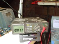
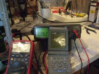
Offset -1.1 mV
Vdrop across 1 of the 0.22 R 0.267
Current trough one supply rail 2.4 A~
Rails at 24.3 V (48.6 V total)
This is nearly a 2 V drop from the previous 26 V rails
2 factors causing this
1 Cable Run from PSU adding a bit more resistance
2 Capacitor bank (new RIFA) 50mF now supplying more current
Because I forgot to mention 2 channels now working on the same heath sink.
I will have a listen tomorrow to ear the difference that going down on current
1.2 A on each mosfet causes from the 2 A of the previous set up.
The restraining factor is the heath sinks, which are dissipating more or less as before 233 Watts
I may be able to gain same voltage back by increasing the Capacitors banks
So each channel has it own.
And maybe if sound quality is much worst try with single mosfets instead of the 2 parallel ones.
PS still running the Toshibas and 10 sometink ma J fets
gain is a bit low.
Help please
Would the change to Farchild and or using 7~mA Jfet increase gain a bit?
http://www.diyaudio.com/forums/swap-meet/182480-holco-mfr-15ppm-2w-sale.html
The F5 playing along 20V peak 1Khz
Same set up but poor pictures to enclose THD 0.098
Will have to get back to that...
Same temperature measurement in the mean time
Top of the worst mosfet case 71.3 C
Copper heat spreaders 63.3
Heath sink 53.7
Worst possible positions (I will be only cheating myself)
I am quite happy with such a small difference between the 3
The effort invested in to the thermal coupling paid off.
I had a mosfet running a bit hotter but a "couple" more turns on the securing nuts cured that
Offset -1.1 mV
Vdrop across 1 of the 0.22 R 0.267
Current trough one supply rail 2.4 A~
Rails at 24.3 V (48.6 V total)
This is nearly a 2 V drop from the previous 26 V rails
2 factors causing this
1 Cable Run from PSU adding a bit more resistance
2 Capacitor bank (new RIFA) 50mF now supplying more current
Because I forgot to mention 2 channels now working on the same heath sink.
I will have a listen tomorrow to ear the difference that going down on current
1.2 A on each mosfet causes from the 2 A of the previous set up.
The restraining factor is the heath sinks, which are dissipating more or less as before 233 Watts
I may be able to gain same voltage back by increasing the Capacitors banks
So each channel has it own.
And maybe if sound quality is much worst try with single mosfets instead of the 2 parallel ones.
PS still running the Toshibas and 10 sometink ma J fets
gain is a bit low.
Help please
Would the change to Farchild and or using 7~mA Jfet increase gain a bit?
http://www.diyaudio.com/forums/swap-meet/182480-holco-mfr-15ppm-2w-sale.html
Attachments
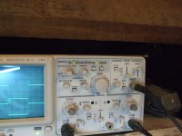
Hi Wayne
In those pictures from the
1 output of the USB Crapyscope (picture of the unclipped output)
2 The puter Audigi Audiophile 192 sound card
On main system
output form Roxan Kandy
or output from Akay SS1
I got a couple of THAT Corporation 8 leged spiders that do single in balanced out and have a handy 6 dB gain to try out
Yes I know the F5 deserve better and "decent" pre is next on to do list
Got the Box but no PCB (hint) for it.
Yess I know I could make the PCB myself but not fair in this case so I am being patient.
Maybe Papa can send same pre production models or old obsolete stock I wont mind if silk screens are a bit wrong and cases are a bit scratched and such
In those pictures from the
1 output of the USB Crapyscope (picture of the unclipped output)
2 The puter Audigi Audiophile 192 sound card
On main system
output form Roxan Kandy
or output from Akay SS1
I got a couple of THAT Corporation 8 leged spiders that do single in balanced out and have a handy 6 dB gain to try out
Yes I know the F5 deserve better and "decent"
pre is next on to do list Got the Box but no PCB (hint) for it.
Yess I know I could make the PCB myself but not fair in this case so I am being patient.
Maybe Papa can send same pre production models or old obsolete stock I wont mind if silk screens are a bit wrong and cases are a bit scratched and suchProgress on my build has been slow but is getting there.
An the F5 is growing and evolving just see Papa mention P3.
I have given it a quick try but to quick a try to have much to say.
In the mean time my 2 mono blocks with separate suplly.
Still 2 parallel mosfet but with Fairchild this time all as F5 manual with no current limiters.
Speaker protection is there for a reason.
I am going to listen to them for a few days
Then fit on more "F5 board" and by Amp and then go balanced.
Maybe new PCB for cascoded Parralel Jfets and P3
Loads to do...
PS.
One thing that was discussed previously was the value of R5 R6 2.2K worked fine with the Toshibas and is still working fine with the Fairchild.
Attachments
Third day of bliss
And I am ready to push things further.
Quote >
Mighty Zen post 28 adding Bass to F5 tread
doubling jfets - I meant on paralleling them : 2 x 2SJ74 + 2x 2SK170
cascoding remains , as measure of voltage umbrella for Jfets , and also useful umbrella for nasty Mr. Miller's liquids.
Question would a small resistor be needed say 33R on the drain of the paralleled J fets ?
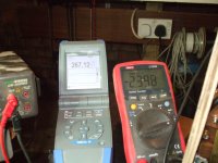
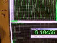
Got same mesuraments of one of the F5 monos
Rail at 31V 2.8 A 10 Homs resistor as load.
THD at 6 VPP 0.0144 eventualy I will learn how to use this new program and be able to post a screen shoot
PS is the Virtinis as in the ZRLC tread
4V PP in 36V PP out
First sign of clipping at -28V on negative rail.
Maybe mat is wrong but say no clipping at 26 V 52 VPP
52 X 52 / 10 = 270 W ????
Bias at 2.8 A so 5.6 X 10 shuld leve class A at 56 W
Plenty of room as 6 Volts is all I need In my room to be plenty loud
I was going to get up in frequency to mesure sine at 10 to 100 KHz and to do that I had to cycle the signal generator on the scope.
this take the frequency up to the MHz before next push of the button set it to 100 KHz.
F5 did not like that and got the speaker protection to activate before lovly smell of burnt resistor mixed feeling about it
1 Crap you silly TW..
2 Yess it broke juppy now I know.
Not big deal got plenty of spares and me think Just a resistor and one maybe 2 J fets gone to Even.
Newer mind got the new Board ready for drilling
If you need proper drawing let me know
Still 2 mosfets rail + Papa cascode maybe 2 parralel J fet and P3 ready
To be continued
Attachments
Power = Volts times Amps = Volts squared divided by Load resistance = Amps squared times Load resistance.
As formulae it looks like this
P = V*I = V^2/R = I^2*R where V and I are the rms values.
Convert your sinewave 52Vpp to Vpk by dividing by 2, gives output voltage = 26Vpk.
Convert the sinewave peak voltage to rms voltage by dividing by sqrt(2) gives output voltage = 18.38Vrms
Output Power = 33.8W, not 270W, nor
If we assume your 28Vpk indicates clip free at 27.9Vpk then maximum output power ~39W
As formulae it looks like this
P = V*I = V^2/R = I^2*R where V and I are the rms values.
Convert your sinewave 52Vpp to Vpk by dividing by 2, gives output voltage = 26Vpk.
Convert the sinewave peak voltage to rms voltage by dividing by sqrt(2) gives output voltage = 18.38Vrms
Output Power = 33.8W, not 270W, nor
313 W peack
If we assume your 28Vpk indicates clip free at 27.9Vpk then maximum output power ~39W
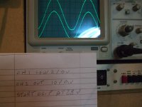
One channel cascoded and 2 pairs of Jfets
tried P3 but couple of mosfets whent pooftsss so desist for now
At first listen between chanels more definition more pleasing Hi frequency bit less harshness even boss said one sound louder the other sound beter bit more melow.
Could not push things as neigbors and her in the house but really really pleased
I will not put numbers on it but on 4 homs speaker.
You can have a good look at my knobs and work it out probably beter than me
crappy scope signal generator square in not that good in chanel 1
Is now in living room plaing Bon Iovy boss likes it and I have penitence to make
PS pre is an old Akay SS1 for now
Attachments
Last edited:
I'm not an EE, but my take is that the Peak power thing is a bit of a red herring.
When describing a sine wave we do have the term peak voltage that describes the highest voltage the waveform will ever reach.
RMS power is the effective value of the total waveform. It is really the area under the curve. (between the midpoint and the two extremes).
Lets say we had a square wave into some imaginary load at 100% duty cycle (I.e. clean DC) We can agree that this is the maximum amount of energy that can be transfered (not that its relevant). Now lets reduce the duty cycle to 50%... The wave form will be high 50% of the time and low 50% of the time so effectively the powe rit is outputing is now only half of what is was before. The peak voltage of the waves is still exactly the same however. I.e. calculating power based on peak voltage is a non-logic thing to do... in my opinion.
Last edited:
- Status
- This old topic is closed. If you want to reopen this topic, contact a moderator using the "Report Post" button.
- Home
- Amplifiers
- Pass Labs
- My F5