More pictures
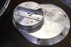
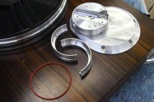
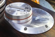
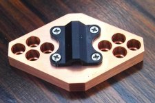
The next three pictures show the Track Housing installed, the two Bezel Halves with their Retaining O-Ring and the Bezel Halves installed.
Ralf
The next three pictures show the Track Housing installed, the two Bezel Halves with their Retaining O-Ring and the Bezel Halves installed.
Ralf
Attachments
What can I say?
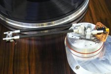
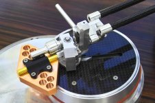
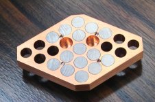
the first of the next three photos shows the Tone Arm and its Carriage inserted into the Track Housing.
The second photo is a close-up of the Carriage.
And the third photo is a close-up of the far side (sorry Gary Larson) of the carriage.
Ralf
the first of the next three photos shows the Tone Arm and its Carriage inserted into the Track Housing.
The second photo is a close-up of the Carriage.
And the third photo is a close-up of the far side (sorry Gary Larson) of the carriage.
Ralf
Attachments
Ho-Hum more photos
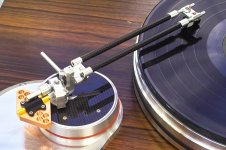
the first of the next five photos shoes the inner half of the Carbon Fiber Cover installed.
The second photo shows both Carbon Fiber Covers installed.
The third photo shows a close-up of the Tone Arm.
The fourth photo shows the far side of the Tone Arm.
And the fifth photo shows a close-up of the far side.
Ralf
Attachments
I guess this is it for a while,
the next three photos are the last.
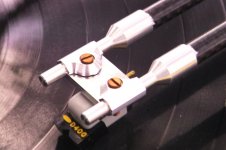
The first photo shows the Orsonic inspired Head shell.
The second photo shows the top of the Counterweight and the third photo shows the bottom of the Counterweight.
The reason for the somewhat strange appearance of the Counterweight is the fact that it cannot be any thicker than .300" if I want to achieve dynamic balance. To get the necessary weight I had to spread it sideways. I made it from copper, laced with diameter 1/4" machinable tungsten rods. The extra holes are for additional Rider Weights for phono cartridges heavier than 6 grams.
the next three photos are the last.
The first photo shows the Orsonic inspired Head shell.
The second photo shows the top of the Counterweight and the third photo shows the bottom of the Counterweight.
The reason for the somewhat strange appearance of the Counterweight is the fact that it cannot be any thicker than .300" if I want to achieve dynamic balance. To get the necessary weight I had to spread it sideways. I made it from copper, laced with diameter 1/4" machinable tungsten rods. The extra holes are for additional Rider Weights for phono cartridges heavier than 6 grams.
Attachments
well, I finally have some photos ready for you. I spent all of Thursday and took thirtyfive pictures, twentysix of which I'll post.
I've assemled the tone arm temporarily without the internal wiring just to take the pictures. The parts are as machined with no finish yet. when the parts are truly finished, I'll have them clear anodized.
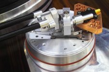
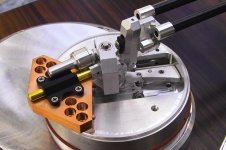
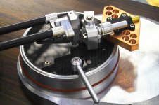
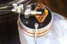
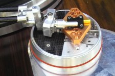
The first three photos show the arm in the Rest, Start and End position on a Micro-Seiki BL-91 L turntable which I purchased in the early eighties. Note the position of the carriage on the cylindrical base.
Sincerely,
Ralf
Wow, this is amazing..

Can't wait to hear about your first impressions of its sound. You've definitely got something here..
Last edited:
Gorgeous work!
Looking at the photos one wonders if you did the machining yourself, or if not how it was done??
Also curious why Tungsten? A hard material to machine, and so why not just steel or lead??
After seeing this, I am still a bit lost on the theory behind the design, so I will have to go back and actually read the article you posted. Does your design still use a sensor and a motor for positioning??
_-_-bear
Great work, Ralf!
I am really happy to see someone consummated the idea of a "pivoted tangential" tonearm in my other thread. It's nice to see an arm without offset angle!
What prompted the idea of using dual armtubes? Does that double the mass, hence the greater horizontal mass along with all the linear bearings? Just curious.
It looks really awesome! Thanks for posting and I look forward to its sonic report.
Hello bear,
I had help from two friends. One is a clock maker and the other one has access to a CNC machine. I made all the parts, that could be made with a manual milling machine. I have no lathe.
The whole Arm was designed as a solid model using CAD.
First of all, I had designed myself into a corner as far as available space was concerned. I had to put as much weight into that space as possible. And that is why I chose tungsten in a copper housing. The tungsten I chose, is a special MACHINABLE kind. It is 97% tungsten with small quantities of iron and nickel. It is made from powdered metal and can be machined with High Speed or Carbide tools. It is almost twice as heavy as lead.
In posts #3 & 4 there is an article written by David Bak, East coast Editor for "Design News". He explained it very well.
At the moment it does not. I will try to use the friction of the rotating LP to "pull" the arm along its track. I know that works. The question is: how accurately?
If it is not accurate, I will use a servo. The Arm is machined with that possibility in mind.
Sincerely,
Ralf
Looking at the photos one wonders if you did the machining yourself, or if not how it was done??
I had help from two friends. One is a clock maker and the other one has access to a CNC machine. I made all the parts, that could be made with a manual milling machine. I have no lathe.
The whole Arm was designed as a solid model using CAD.
Also curious why Tungsten? A hard material to machine, and so why not just steel or lead??
First of all, I had designed myself into a corner as far as available space was concerned. I had to put as much weight into that space as possible. And that is why I chose tungsten in a copper housing. The tungsten I chose, is a special MACHINABLE kind. It is 97% tungsten with small quantities of iron and nickel. It is made from powdered metal and can be machined with High Speed or Carbide tools. It is almost twice as heavy as lead.
After seeing this, I am still a bit lost on the theory behind the design, so I will have to go back and actually read the article you posted.
In posts #3 & 4 there is an article written by David Bak, East coast Editor for "Design News". He explained it very well.
Does your design still use a sensor and a motor for positioning??
At the moment it does not. I will try to use the friction of the rotating LP to "pull" the arm along its track. I know that works. The question is: how accurately?
If it is not accurate, I will use a servo. The Arm is machined with that possibility in mind.
Sincerely,
Ralf
Hello kevinkr,
Thank you.
My Hi-Fi system got into disarray over the years. The cones in my Koss speakers just disintegrated in the Arizona air.
When I built that Tone Arm, I saw myself confronted with having to replace my speakers. I also am getting a new Soundsmith cartridge because my old Shure V 15 ( or something like that ) is probably dried out too.
I have high frequency hearing damage from unprotected shooting of 105mm and 155mm Howitzers in the Canadian Artillery in the Sixties.
So, the final judgement as to how well this Tone Arm sounds will have to be made by younger people with better ears.
My plan is to take it to Phoenix, to a High-End store to see if someone will do that for me.
Sincerely,
Ralf
Wow, this is amazing..
Can't wait to hear about your first impressions of its sound. You've definitely got something here..
Thank you.
My Hi-Fi system got into disarray over the years. The cones in my Koss speakers just disintegrated in the Arizona air.
When I built that Tone Arm, I saw myself confronted with having to replace my speakers. I also am getting a new Soundsmith cartridge because my old Shure V 15 ( or something like that ) is probably dried out too.
I have high frequency hearing damage from unprotected shooting of 105mm and 155mm Howitzers in the Canadian Artillery in the Sixties.
So, the final judgement as to how well this Tone Arm sounds will have to be made by younger people with better ears.
My plan is to take it to Phoenix, to a High-End store to see if someone will do that for me.
Sincerely,
Ralf
hello gninnam,
Thank you.
I hope you're right.
Sincerely,
Ralf
Looks fantastic
I am sure it will deliver the goods
Thank you.
I hope you're right.
Sincerely,
Ralf
hello GoranB,
Thank you GoranB
It is intense work, but it's worth it when you see the results.
Sincerely,
Ralf
You are doing a great job there, thanks for your efforts to improve things in analoge source audio.
Thank you GoranB
It is intense work, but it's worth it when you see the results.
Sincerely,
Ralf
Last edited:
Hello directdriver,
Thanks for the kind words. I've read your entire other thread. I posted a comment as to how amazed I was that anyone could gather as much information on tangential tone arms as you have.
I'm quite sure that you must know what the "Orsonic Head Shell" is? That head shell has a machined portion which joins the single tone arm tube to the two shafts that project forward to support the cartridge mounting platform. In my opinion that places too much mass near the head shell. So I decided to move that mass as close to the tone arm pivot as possible. That in turn requires the two shafts to be extended toward the tone arm pivot, thus, two arm tubes.
Before I designed my Tone Arm, I looked at as many of the existing tone arms that used carbon fiber tubes as I could and I determined that they were using tubes of aproximately .400" Diameter. I then figured out what diameter two tubes would have to be in order to equal the mass of a single larger tube. So, the short answer is: no, it did not double the mass.
There are no linear bearings in my Tone Arm. The carriage rides on four ABEC 7 ball bearings on two stainless steel shafts. The Tone Arm pivots on two "Free Flex pivots" in the horizontal plane and two "Free Flex pivots" in the vertical plane.
Sincerely,
Ralf
directdriver;2518947]Great work, Ralf!
I am really happy to see someone consummated the idea of a "pivoted tangential" tonearm in my other thread. It's nice to see an arm without offset angle!
Thanks for the kind words. I've read your entire other thread. I posted a comment as to how amazed I was that anyone could gather as much information on tangential tone arms as you have.
What prompted the idea of using dual armtubes?
I'm quite sure that you must know what the "Orsonic Head Shell" is? That head shell has a machined portion which joins the single tone arm tube to the two shafts that project forward to support the cartridge mounting platform. In my opinion that places too much mass near the head shell. So I decided to move that mass as close to the tone arm pivot as possible. That in turn requires the two shafts to be extended toward the tone arm pivot, thus, two arm tubes.
Does that double the mass, hence the greater horizontal mass along with all the linear bearings? Just curious.
Before I designed my Tone Arm, I looked at as many of the existing tone arms that used carbon fiber tubes as I could and I determined that they were using tubes of aproximately .400" Diameter. I then figured out what diameter two tubes would have to be in order to equal the mass of a single larger tube. So, the short answer is: no, it did not double the mass.
There are no linear bearings in my Tone Arm. The carriage rides on four ABEC 7 ball bearings on two stainless steel shafts. The Tone Arm pivots on two "Free Flex pivots" in the horizontal plane and two "Free Flex pivots" in the vertical plane.
Sincerely,
Ralf
Last edited:
Ur gonna drag the carriage forward using the stylus to pull it? Not sure if that is what you said?
The other thing, is does the carriage slide forward and back depending on the leveling of the TT? How about if the floor bounces (yeah not a good thing if it does, but...).
Once it starts to move forward, what prevents "overshoot"? Or, why is it not perpetually either just ahead or just behind the proper spot in the groove? With a conical stylus, perhaps not a big issue, but with one of the faceted stylus geometries, this could become an issue.
Overcoming the static friction of the little ball bearings might be an issue.
How about "anti-skate" does this play a role, since the arm can still pivot?
Straight Tracker:"I'm quite sure that you must know what the "Orsonic Head Shell" is?"
Yes, I am familiar with the Orsonic headshell because I have one myself. Neat design. I think as long as the total mass is not much greater than a single armtube there should not be a problem.
Straight Tracker: "There are no linear bearings in my Tone Arm. The carriage rides on four ABEC 7 ball bearings on two stainless steel shafts."
I think it's a matter of semantic. What I had in mind was any bearing on a carriage that glides with horizontal mass is linear bearing, instead of the traditional shaft and bushing type of linear bearing. Essentially anything that does not pivot. One design in my head was similar but using a tricycle type of carriage, as shown in my thread, using the front third wheel as a guide to keep the cartridge following the Thales circle.
Thanks for the explanations and thank you for advancing the analog art!
.
Hello bear,
You read it right bear! Years ago I read an article in the Journal of the Audio Engineering Society, stating that the coefficient of friction of a stylus gliding in a V-groove is typically 0.5 to 0.25. The coefficient of friction of ABEC-7 bearings rolling on hard steel shafts is 0.04. under those conditions the rotating LP can easily pull a tone arm and its carriage. Initial tests show that it actually works.
I have not done any tests yet as to how finnicky that set-up will be.
Those are very good questions. you are obviously paying attention.
When the tone arm is initially set up, it should be accurately leveled or very slightly inclined toward the platter so that the tone arm carriage has a definite tendency to move toward the platter when the Arm is actually tracking an LP. There is a mechanism in the base of the Tone Arm that applies a force to the carriage that is equal and opposite to the frictional force trying to pull the carriage toward the platter. This opposing force must continuously increase as the Tone Arm pivots toward the center of the LP. The rate of increase is a funtion of the cosine of the angle between the center line of the Tone Arm and the center line of the track. Thirty years or so ago when the Arm was patented, I solved that problem with a bell shaped weight being lifted from an oil-filled container. However, that idea suffered from a lack of adjustability. In my present Tone Arm I found a way to make that force adjustable from the outside.
As you know, skating is caused by an offset head shell whose theoretical center line does not pass through the tone arm pivot.
Most tangential tone arms have a head shell in line with the pivot of the arm and therefore do not skate. That is, except the Garrard Zero 100 and the Thales as far as I know.
So you can see, that a tone arm that is shorter ( 7.950" ) with the absolute shortest carriage travel ( 1.550" ) and no skating forces, is at least theoretically, the best solution.
Sincerely,
Ralf
Ur gonna drag the carriage forward using the stylus to pull it? Not sure if that is what you said?
You read it right bear! Years ago I read an article in the Journal of the Audio Engineering Society, stating that the coefficient of friction of a stylus gliding in a V-groove is typically 0.5 to 0.25. The coefficient of friction of ABEC-7 bearings rolling on hard steel shafts is 0.04. under those conditions the rotating LP can easily pull a tone arm and its carriage. Initial tests show that it actually works.
The other thing, is does the carriage slide forward and back depending on the leveling of the TT? How about if the floor bounces (yeah not a good thing if it does, but...).
I have not done any tests yet as to how finnicky that set-up will be.
Once it starts to move forward, what prevents "overshoot"? Or, why is it not perpetually either just ahead or just behind the proper spot in the groove?
Those are very good questions. you are obviously paying attention.
When the tone arm is initially set up, it should be accurately leveled or very slightly inclined toward the platter so that the tone arm carriage has a definite tendency to move toward the platter when the Arm is actually tracking an LP. There is a mechanism in the base of the Tone Arm that applies a force to the carriage that is equal and opposite to the frictional force trying to pull the carriage toward the platter. This opposing force must continuously increase as the Tone Arm pivots toward the center of the LP. The rate of increase is a funtion of the cosine of the angle between the center line of the Tone Arm and the center line of the track. Thirty years or so ago when the Arm was patented, I solved that problem with a bell shaped weight being lifted from an oil-filled container. However, that idea suffered from a lack of adjustability. In my present Tone Arm I found a way to make that force adjustable from the outside.
How about "anti-skate" does this play a role, since the arm can still pivot?
As you know, skating is caused by an offset head shell whose theoretical center line does not pass through the tone arm pivot.
Most tangential tone arms have a head shell in line with the pivot of the arm and therefore do not skate. That is, except the Garrard Zero 100 and the Thales as far as I know.
So you can see, that a tone arm that is shorter ( 7.950" ) with the absolute shortest carriage travel ( 1.550" ) and no skating forces, is at least theoretically, the best solution.
Sincerely,
Ralf
Last edited:
Hey Ralf,
I am surprised at your report as to the friction of the grade 7 bearings on the steel rods... I hope that number includes the rotation of the bearing and not just the contact between the bearing surface and the rod??
Ok, I dunno how it will sound, but if nothing else it is one heck of a kewl implementation!
Btw, I sent you a PM, you might want to check them if ur not used to doing that?
_-_-bear
- Status
- This old topic is closed. If you want to reopen this topic, contact a moderator using the "Report Post" button.
- Home
- Source & Line
- Analogue Source
- My 1980's Tangential Tone Arm and my 2010 improvement