Glad you have still been working on the design Ralf")
You are right about the relationship between the counter weight and the distance from the pivot based on the weight of the counter weight (to many weights in there......)
You want to make sue that it is not to far out as it will affect the inertia of the arm/cartridge as it is being pulled across the groove possibly causing more drag and oscillations??
I went from brass to copper for the counterweight but couldn't get the center of gravity low enough without interfering with the base of the tone arm. I finally remembered machinable tungsten alloy which has a specific gravity of 18.5 grams per cubic centimeter.
Interesting you mention those materials.... My yoke is OFC because of a lot of things, including the 'bling' factor. I think copper looks fantastic. It also has less 'ring' to it than brass (particularly bell brass) so it is a bit easier to keep under control. I have optimized shape and interfaces to keep as much of the resonance under control as I can. I am currently looking into various 'clear coatings' which will preserve the appearance as well as further damp high frequency resonance.
Another thought for you might be a cavity in your brass to accept some molten lead or tin (plain old plumber's solder to test!)
It took some time to find a supplier who would sell me a small quantity.
Is it 'pure'? I have access to thoriated (not a wise choice) and lanthinated tungsten. The latter will likely find use in my counterweight.
I do the necessary calculations in my CAD program so that I don't actually have to make experimental counterweights.
Very cool! I have access to Inventor, but I use AutoCad Lite, which can do some calculations but in general it is faster (for a math lackey like me) to make what 'looks' right and try it. I have access to a lot of scrap material, so I can play a bit without going totally broke...
I did discover something though that everyone else probably already knows:
You can have a counterweight of a given mass 3" behind the tone arm pivot or you can have a counterweight of a greater mass 2" behind the tone arm pivot. the question is: how do you optimize that relationship?
That is a good question! In your design I could not even imagine how to answer that; however I will throw some info out there you may find interesting. (below pertains to typical tonearms, so keep that in mind)
1) Having the weight 'heavier' and closer to the pivot point is generally regarded as a good idea. When the weight is further away, it is acting on a lever of course, which places another moment onto the bearings of the arm. Keeping the weight close in effectively mass-couples the counterweight to the yoke, thereby reducing some sympathetic vibrations which may occur. (bottom line: it sounds better that way)
1a) These sympathetic vibrations can detract from the music program, on varying degrees. One "solution" that is popular with some is to 'decouple' the weight by having an elastomer between the weight and arm. In my opinion, this tends to 'deaden' the sound, so if your arm is overly lively, you may want to investigate this.
2) have the center of gravity of the weight in line with the record surface. If you look at the RB300 for example, there are quite a few mods available for this arm. One is to lower the weight's CoG and increase it's mass and move it in closer to the yoke. Both Michell Engineering and others make a 'low' weight. Several reviewers (and myself) appreciate the positive change this brings.
3) Arm stiffness. This could be a white paper in itself. I went with carbon, like you. It has fantastic weight to stiffness ratio and is cheap these days. The problem is, it rings like steel. I Designed the 'ultimate' carbon tonearm tube, but the prototype was/is $1000.00, so that got back-burnered... I got 'around' this ringing in a conventional carbon tube by using a very slender tube and using the (Teflon insulated) Litz-braided wire to effectively damp the arm tube. There have been arguments for 'bent' (S or L shaped arm tubes) because the bent arm does not resonate the same as a straight one. However, as you increase the path from the shortest (straight) to longer (bent) you increase mass of the arm as well (possibly not linearly either as the stiffness goes down proportionately with length increase of the same tube). If the mass is too high, you limit the cartridges you can use.
Jim Leach, you're the first one to have discovered my use of "Free Flex Pivots" or weird rotary spring things as you call them.
I'm going to use them in my new Arm also. for both the horizontal and vertical bearings, four in all.
Well, I'd like some more info so I could contact the manufacturer. Since I have a basic yoke design, I am using ceramic ball/steel race bearings (dry). VERY low friction/sticktion but there is some of course. I don't know if those rotary springs have enough range of motion for me (maybe one could be nested in another for more range???)

Isn't tonearm design fun!
Hello Jim Leach
I'm machining a copper weight with nineteen 1/4" diameter x 1/4" deep holes machined into it. Then I will loctite nineteen Tungsten weights into the holes which will give me a total weight of 108 grams.
It contains 97% Tungsten, 2.1% nickel and .9% Iron and weighs 18.5 grams per cubic centimeter
Here are links to manufacturers of Flex Pivots:
http://www.c-flex.com, Flexural Pivot Bearings for Frictionless Applications - Riverhawk, and http://www.goodrichrome.com/pivots/
I purchased mine from c-flex. I think their prices were lower.
Even though, the bearings cost approximately $ 45 each.
I use two of them to pivot the Tone Arm in the horizontal plane and I use two to pivot the Arm in the vertical plane. I developed a mechanism that allows me to twist the latter bearings to apply the tracking force.
Nesting the bearings would work fine but would double the cost.
Sincerely,
Ralf
Another thought for you might be a cavity in your brass to accept some molten lead or tin (plain old plumber's solder to test!)
I'm machining a copper weight with nineteen 1/4" diameter x 1/4" deep holes machined into it. Then I will loctite nineteen Tungsten weights into the holes which will give me a total weight of 108 grams.
Is it 'pure'?
It contains 97% Tungsten, 2.1% nickel and .9% Iron and weighs 18.5 grams per cubic centimeter
Well, I'd like some more info so I could contact the manufacturer. Since I have a basic yoke design, I am using ceramic ball/steel race bearings (dry). VERY low friction/sticktion but there is some of course. I don't know if those rotary springs have enough range of motion for me (maybe one could be nested in another for more range???)
Here are links to manufacturers of Flex Pivots:
http://www.c-flex.com, Flexural Pivot Bearings for Frictionless Applications - Riverhawk, and http://www.goodrichrome.com/pivots/
I purchased mine from c-flex. I think their prices were lower.
Even though, the bearings cost approximately $ 45 each.
I use two of them to pivot the Tone Arm in the horizontal plane and I use two to pivot the Arm in the vertical plane. I developed a mechanism that allows me to twist the latter bearings to apply the tracking force.
Nesting the bearings would work fine but would double the cost.
Sincerely,
Ralf
Last edited:
Ralf,
Interesting design. I work with the Marketing department at Riverhawk Flex Pivots and discovered this thread. For the pivot history. Riverhawk purchased the product line from Goodrich. Our line is the original line that has made its way through Lucas Aerospace, Bendix, Goodrich and others. If you can post the part number I'll see what I can do to be of any assistance for future any prototypes. To help your design along if there are further questions regarding flex pivots our engineers are free of charge and available to you.
Thanks,
Adam
Riverhawk Flex Pivots
"Why settle for less when you can spec the original"
Contact me directly via adam.herringshaw@riverhawk.com
Hello ajhawk
It is truly a small world.
In my original Tone Arm from the Eighties I used flex pivots from Bendix.
I used the pivots for motion in the vertical plane. And by twisting the pivots a contolled amount, I used them to also apply tracking force up to 3 grams. I wanted to use the pivots for tone arm motion in the horizontal plane but couldn't figure out how to prevent them from "winding up" during the approximately 20 degrees of horizontal tone arm motion. In the latest version of my Tone Arm, I solved that problem. The equivalent part numbers of the pivots are: 2 each 5004-800 and 2 each 5005-600.
Sincerely,
Ralf
It is great to see OEM support here on DIY audio!
Agree - what a great offer of assistance
News
Hello All,
I promised photos and updates this week. But as you can see, I lied.
In the last two days I've reconditioned my Micro-Seiki turntable with fresh oil in the main bearing and I replaced the belt. It looks like it did when it was new. Then I assembled the Tone Arm and mounted it on the turn table. Tomorrow I'll take a series of pictures which should be posted by Monday.
sincerely,
Ralf
Last edited:
Hello bear
I don't think "swift" or not has anything to do with it.
Sometimes the simplest ideas are not easy to get accross. I try, but I'm not particularly good at explaining things.
All tangential tone arms I know take up lots of space and some turn tables simply don't have enough of that available.
I wanted a tangential tone arm that could be installed in the same space as any ordinary pivoting arm.
The length of the track of my Tone Arm is 1.550" thus any noise generated by the movement of the carriage would be more than an octave lower than other linear arms except air bearing types.
Also, I wanted a tangential tone arm that didn't have the high horizontal effective mass that the air bearing types have.
In addition, I wanted to use "flexural pivots" for the horizontal and vertical pivots. To my knowledge noone has done that. "flexural pivots" have no free play, no friction and don't need to be lubricated.
As far as compexity is concerned, that pertains to the original proto type.
As stated my new version tries to eliminate some or all of that complexity
Sincerely,
Ralf
I'm not swift on the uptake
I don't think "swift" or not has anything to do with it.
Sometimes the simplest ideas are not easy to get accross. I try, but I'm not particularly good at explaining things.
All tangential tone arms I know take up lots of space and some turn tables simply don't have enough of that available.
I wanted a tangential tone arm that could be installed in the same space as any ordinary pivoting arm.
The length of the track of my Tone Arm is 1.550" thus any noise generated by the movement of the carriage would be more than an octave lower than other linear arms except air bearing types.
Also, I wanted a tangential tone arm that didn't have the high horizontal effective mass that the air bearing types have.
In addition, I wanted to use "flexural pivots" for the horizontal and vertical pivots. To my knowledge noone has done that. "flexural pivots" have no free play, no friction and don't need to be lubricated.
As far as compexity is concerned, that pertains to the original proto type.
As stated my new version tries to eliminate some or all of that complexity
Sincerely,
Ralf
To all patient waiters,
well, I finally have some photos ready for you. I spent all of Thursday and took thirtyfive pictures, twentysix of which I'll post.
I've assemled the tone arm temporarily without the internal wiring just to take the pictures. The parts are as machined with no finish yet. when the parts are truly finished, I'll have them clear anodized.
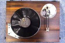
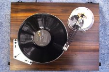
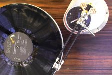
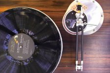
The first three photos show the arm in the Rest, Start and End position on a Micro-Seiki BL-91 L turntable which I purchased in the early eighties. Note the position of the carriage on the cylindrical base.
Sincerely,
Ralf
well, I finally have some photos ready for you. I spent all of Thursday and took thirtyfive pictures, twentysix of which I'll post.
I've assemled the tone arm temporarily without the internal wiring just to take the pictures. The parts are as machined with no finish yet. when the parts are truly finished, I'll have them clear anodized.
The first three photos show the arm in the Rest, Start and End position on a Micro-Seiki BL-91 L turntable which I purchased in the early eighties. Note the position of the carriage on the cylindrical base.
Sincerely,
Ralf
Attachments
Ditto
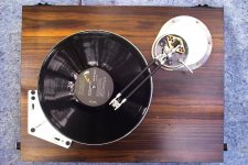
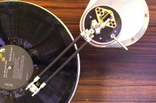
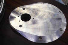
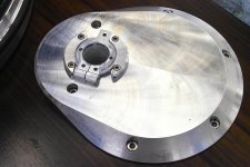
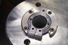
the first of the next four photos shows the Mounting Base for the tone arm assembly.
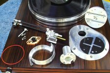
The second photo shows all the components ready to be assembled.
The third photo shows the Bearing Housing installed and the fourth photo shows a close-up the third photo.
ralf
the first of the next four photos shows the Mounting Base for the tone arm assembly.
The second photo shows all the components ready to be assembled.
The third photo shows the Bearing Housing installed and the fourth photo shows a close-up the third photo.
ralf
Attachments
- Status
- This old topic is closed. If you want to reopen this topic, contact a moderator using the "Report Post" button.
- Home
- Source & Line
- Analogue Source
- My 1980's Tangential Tone Arm and my 2010 improvement