Hi Bardos,
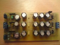
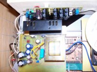
This is the PCB i will use for testing your DAC PSU, I cant say its the best designed PCB but in the lack of time i did my best. All i have to do is to connect it to the DAC. I hopw ill find out the reason for voltage drop phenomenon.
Best regards
Goran
This is the PCB i will use for testing your DAC PSU, I cant say its the best designed PCB but in the lack of time i did my best. All i have to do is to connect it to the DAC. I hopw ill find out the reason for voltage drop phenomenon.
Best regards
Goran
Attachments
Hello Bardos,
I tested the power supply unloaded, instead of 1K on the base of BC550/560 i use trimer potentiometers of 5K, bicause i have only that value. It works ok, i can setup the voltage -15V, -5V, +5V very precisly. You can solder high turn potentiometers of value of 2K and all will be fine. I use the trafo 17V/60VA. Now i will try to connect it to the DAC.
Regards
Goran
Hi Bardos,
I can suggest you to buy a trafo 0-17V/30VA, should not be expencive. and your board will work also. If you are interested, i can make you a board and send it to you. Im planing to change all regulators i have with this PS, so i will make severall boards. If you want i will make for you also without any charge.
Regards
Goran
Hi,
The next will be changeing all LM's and 78XX, 79XX with PS you sent me.
About board, its not a problem at all, you can have not just one. Just ill be able to make them after ill came back to Poland, it means after 2 weeks.
Send me your adress, now or when ill back.
It will be if you can tell me the size of caps you want to use, so i could design your boards.
For 7220 it can be used also but with some changes.
Regards
Goran
Hello Bardos,
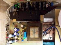
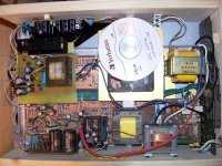
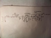
Durring night i have designed the PS PCB for SAA7220, the same circuit as for +5V of the led PS. It will have separated trafo and different transitors, in this case i will use J13009 mounted on the small heatsinks. For filtering caps I will use 10.000uF/25V, 2200uF/35Vx2, 220uF/63V Vishay x 2, and Silmics II 100uF/35V. The trafo will be mounted on the PCB also, the voltage on the secundar is 11V.
This morning Im going to solder the components and I hope ill have time to try if it works.
Ill send you photos when it will be done.
Best regards
Goran
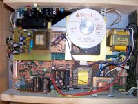
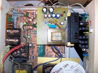
Bardos, things get complicated a little, i already have 4 trafo's inside CD player, the best would be to build separated box for the trafo's. I should find or build some nice metal box for that purpose, but for now im just testing so ill stay with the box i have. also i will need to make better transport, the problem with that is that flat cable is too short, im not sure if its a good idea to make it longer and install the transport on the top of the enclosure.
Maybe you have some experience about that, i mean if the longer flat cable could produce some problems?
Regards
Goran
Maybe you have some experience about that, i mean if the longer flat cable could produce some problems?
Regards
Goran
This thread is excellent")
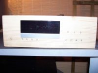
Thanks. I hope You really like it. My intention is to improve the Marantz CD40 with help from members of this forum. At this stage its just testing project as You can see from the photos. The finall product will look much better, with new enclosure and better boards and components.
Hi
I too have a phillips based cd player with separate 7805's dedicated to SAA7220, 7310 and Ram Chips. I have been looking for ways to improve this simple arrangement.
Would you make additional boards and maybe sell them to other members like me ?
Your boards are an excellent solution but would understand if it's not practical do to this
I am also learning quite a bit from this valuable thread and can already implement some changes from your advice so far - keep going !!
Thanks
Hi Goran Nice job on the PSU and the box look very cool. Thanks for the 7220 ps. So the BD139 seems to work right. I will try out as soon as I fixed the Nad 3020.
Thanks Bardos, We both know its not so cool
, but just wait when ill finish all mods and tests I already have plans for new really cool box. Yes the BD139 works great. Its turned on for 24 hours and it works perfect. Really great improvement. Just as I suggest you will need a heatsinks for both transistors. You can also use BD139 instead of J13009, or some really fast transistors. Regards Goran- Status
- This old topic is closed. If you want to reopen this topic, contact a moderator using the "Report Post" button.
- Home
- Source & Line
- Digital Source
- mutting transistors on the output of Marantz cd40 help!!!