Hi there
Is a bit early but I was thinking about sourcing parts at faworable cost
A couple of questions about the:
BC 327 it does came in different flawors with hfe from 100 to 200 cassification 16
From 160 to 400 classification 25
from 250 to 630 classification 40
Which one of the groups would be beter for the paradise.
I am thinking of a bulk purchase of 1000
I am not doing this to make a profit so if any one wants my contact let me know
othervise provided there is enoug demand I am prepared to go ahead.
Same all aplies to the BC 337
Another question is wher it would be most beneficial to use expensive resistors
I am planing on RC55Y but maybe a few Z foils may be beneficial most probably around the RIAA filters and such
what would be the best place to trow serious money on it?
Last edited:
Bksabath, we use BC327-40 and BC337-40, the highest Hfe type.
Frans has a very good source for this transistors in good quality. The transistors from my source did not match well and had double the price.
Ricardo and Hesener, i will check the board again for bugs. i will need some time to do this.
Ricardo, yes, this Lyra paper explains the loading phenomenon rather well.
The BC's I got from:
Search results | SOS electronic
When we are ready to do the GB we should take inventory on orders and then we could get a good number of those. There is a minimum order value before they will process the order.
Search results | SOS electronic
When we are ready to do the GB we should take inventory on orders and then we could get a good number of those. There is a minimum order value before they will process the order.
Frickelfest
To Holger (our host), and all the other very nice people at Frickelfest,
Thanks for allowing me to attend, it was a real pleasure to be there, I am real happy (and was that all the way home) with the compliments and interest that I and my phono stage received.
Next time I will bring it again and we can compare it with many Paradise builds. So you may count on me, there will be a next time.
Thank you all, I’m still happy")
Regards,
Frans.
To Holger (our host), and all the other very nice people at Frickelfest,
Thanks for allowing me to attend, it was a real pleasure to be there, I am real happy (and was that all the way home) with the compliments and interest that I and my phono stage received.
Next time I will bring it again and we can compare it with many Paradise builds. So you may count on me, there will be a next time.
Thank you all, I’m still happy
Regards,
Frans.
oops, sounds like the boards have the wrong values printed.... thanks for highlighting. I think I remember that there was some conversation around these resistors and that 10/22 was the final "verdict", so I must have changed them in the schematic but not on the PCB. Anyhow, maybe MiiB or Joachim can confirm so I can fix this bug, would be great!
I already populated all the resistors and transistors according to the schematics that states R47 = R51 = 22r Maybe I need to remove those and order the correct ones. Please let us know the final values... Is R47 different from R 51 ?
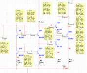
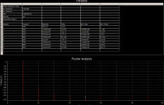
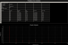
I promised some ideas, regarding basic building blocks (mirrors and buffers in particular) of phono stages that we are discussing here, so here it goes… I know you Joachim are crazy about buffers, so I can understand that this paradise mirrored driven diamond cascode (or whatever you can call it) in all it’s glory is really excellent, but is it not over engineered a bit ? This is not a problem at all with current el cheapo parts, but it sure looks like it could go straight to space (ATL labs put a hand on it I’m sure ). Now the way I see it, largest non linearity's (and hence thd) arises from our beloved current mirrors. Although helper transistors do help with beta matching and further cascoding reduces base current modulation, early voltage effects are still visible even in sim’s. So I gave a thought or two about addressing these issues. One could through GNFB loop around it and call it a day (look ma, no thd! at last I have ideal components!), but that is what I personally would call bad practice and it's like fighting birds with ballistic missiles. Now I'm sure there is a couple more ways to skin this cat, but this one I actually saw implemented in one peace of very expensive measuring gear, that I had for repair. I will be honest here, I didn't get it at first sight, and thought it was just kind of bootstrapping buffer, but yesterday I remembered this piece of circuit, took that repair manual again and clearly this was error correction. I don't know if I have to go step by step here on how it works, as I'm sure most of you can figure that out just by looking at attached pic, but the basic idea behind this trick is to keep the net value of incoming and outgoing currents from mirrors to 1 by introducing “lost” base currents. What we have here is simple cascoded current mirror and addition of Q33, Q44 that runs at 2 times more current then mirrors, introducing approximately 2 times base currents for correction and bootstrapping Q53 who ensures that Q33 Vce stays constant, hence no base current modulation occurs. But the best part of it (cherry on top) is that you get quite a buffer for bonus that can swing 1Vrms to 600 Ohms all day long almost without any significant increase in thd. Headroom is also increased from 22Vpp in original paradise running from 24V rails to 32Vpp on only 18V rails before clipping. Now that is a clever piece of engineering or what ? 3 in 1 as they say. I attached thd sim’s for current paradise version and paradise front end with error correction + buffer. It works in theory and I’m sure in practice to some extend as well. Device power dissipation can be solved with paralleling (I didn't wonted to spoil the picture) and hfe matching (except maybe Q53) is a must.
I have to put a disclaimer here that this is not a bashing of great design, and I’m not proposing to implement this to current release of paradise, as this would require a lot of remaking for psu and pcb’s. Just a food for thought as how things could be made more optimal in future.
). Now the way I see it, largest non linearity's (and hence thd) arises from our beloved current mirrors. Although helper transistors do help with beta matching and further cascoding reduces base current modulation, early voltage effects are still visible even in sim’s. So I gave a thought or two about addressing these issues. One could through GNFB loop around it and call it a day (look ma, no thd! at last I have ideal components!), but that is what I personally would call bad practice and it's like fighting birds with ballistic missiles. Now I'm sure there is a couple more ways to skin this cat, but this one I actually saw implemented in one peace of very expensive measuring gear, that I had for repair. I will be honest here, I didn't get it at first sight, and thought it was just kind of bootstrapping buffer, but yesterday I remembered this piece of circuit, took that repair manual again and clearly this was error correction. I don't know if I have to go step by step here on how it works, as I'm sure most of you can figure that out just by looking at attached pic, but the basic idea behind this trick is to keep the net value of incoming and outgoing currents from mirrors to 1 by introducing “lost” base currents. What we have here is simple cascoded current mirror and addition of Q33, Q44 that runs at 2 times more current then mirrors, introducing approximately 2 times base currents for correction and bootstrapping Q53 who ensures that Q33 Vce stays constant, hence no base current modulation occurs. But the best part of it (cherry on top) is that you get quite a buffer for bonus that can swing 1Vrms to 600 Ohms all day long almost without any significant increase in thd. Headroom is also increased from 22Vpp in original paradise running from 24V rails to 32Vpp on only 18V rails before clipping. Now that is a clever piece of engineering or what ? 3 in 1 as they say. I attached thd sim’s for current paradise version and paradise front end with error correction + buffer. It works in theory and I’m sure in practice to some extend as well. Device power dissipation can be solved with paralleling (I didn't wonted to spoil the picture) and hfe matching (except maybe Q53) is a must. I have to put a disclaimer here that this is not a bashing of great design, and I’m not proposing to implement this to current release of paradise, as this would require a lot of remaking for psu and pcb’s. Just a food for thought as how things could be made more optimal in future.
Attachments
My schematic says R47 = 10 Ohm R51 = 15 Ohm
so they are different
This resistors set bias in the output stage so there is 50% more voltage over the 15 Ohm resistor
That affects output DC offset, that is corrected by the servo anyway.
Say 2mA flow over the 10 Ohm so we have Ube plus 10 Ohm x 2mA = 0,65V plus 0,02V = 0,67 V. That develops also from base to output in the output so the output idles at 1,333mA. You can calculate the same in the other polarity with 15 Ohm. Ube can be different in NPN and PNP transistors though. That values look a bit off to me because the input stage would idle more then the output stage that may have a harder load to drive. 22 Ohm seems to be more correct.
Sampler, i have to digest it but error feed forward is a great way to do it. I can make a better mirror too then in the Pardise but i decided on moderate output impedance because of DC offset issues.
What i would really like to see is your design in parallel symmetric ( if better or necessary ) with a balanced, differential input stage. J-Fet input or not. If we only use N-Channels this is not a component sourcing problem anyway. We can call that the Starless-Balanced and i would 100% support that design.
What i would really like to see is your design in parallel symmetric ( if better or necessary ) with a balanced, differential input stage. J-Fet input or not. If we only use N-Channels this is not a component sourcing problem anyway. We can call that the Starless-Balanced and i would 100% support that design.
My schematic says R47 = 10 Ohm R51 = 15 Ohm
so they are different
This resistors set bias in the output stage so there is 50% more voltage over the 15 Ohm resistor
That affects output DC offset, that is corrected by the servo anyway.
Say 2mA flow over the 10 Ohm so we have Ube plus 10 Ohm x 2mA = 0,65V plus 0,02V = 0,67 V. That develops also from base to output in the output so the output idles at 1,333mA. You can calculate the same in the other polarity with 15 Ohm. Ube can be different in NPN and PNP transistors though. That values look a bit off to me because the input stage would idle more then the output stage that may have a harder load to drive. 22 Ohm seems to be more correct.
So R47 = 10 and R51 = 22 ??