For those of you who wanna have a glimpse at what has taken place at the Frickelfest light: Endspiel
You may also spot our ATL contact guy Frans.
Was a pleasure to meet you, Frans, hope to see you again.
And I have to agree to Joachim: We had a really fantatstic sound. Apart from that, it was great fun and lots of interesting people.
Great warm up for the big Frickelfest in June.
I am speachless .....
I plan a gathering anyway where we all come together and listen.
If it's on this planet, count me in
Audiofanatic
This is an interesting paper on low level distortion in BJT transistors :http://www.essex.ac.uk/csee/research/audio_lab/malcolmspubdocs/J7 Fuzzy distortion.pdf
Thanks Joachim and Holger for details and photos. It must have been nice meeting!
I also missed somehow 2011 ETF photos - also some of these are inspiring! Thanks for reminder Joachim. Nada from Klang Ton is something similar to what I use everyday. Mine is slightly different scan drivers and enclosure - also very thick/stiff and well damped. Still in 'prototype-like' build, but the sound is very fine. Not my design but seemed well designed and works as advertised. If only I knew Nada maybe mine choice would have been different... I use Scan kevlar midbass drivers which are way better than those used by Bowers - though you can here that people complain in general on kevlar drivers...
I also missed somehow 2011 ETF photos - also some of these are inspiring! Thanks for reminder Joachim. Nada from Klang Ton is something similar to what I use everyday. Mine is slightly different scan drivers and enclosure - also very thick/stiff and well damped. Still in 'prototype-like' build, but the sound is very fine. Not my design but seemed well designed and works as advertised. If only I knew Nada maybe mine choice would have been different... I use Scan kevlar midbass drivers which are way better than those used by Bowers - though you can here that people complain in general on kevlar drivers...
What about the 40Vraw psu ?
The 40V raw DC is fine for me, we need 24V for the preamp, this gives 16V for the regulator to play with.
The current source is using up 5V and the voltage source needs 4V at the least, 5V is best (I think).
From this we can conclude that the minimum raw DC needed is 34V (optimal 35V).
And that leads to a transformer voltage of:
(35V + 2V(rectifiers)) / sqrt(2) = 26.1V (this will also vary a bit with capacitor size).
The minimum transformer voltage is thus 25V (using schottky rectifiers) but it is on the low side for the voltage regulator, you van improve this a bit by using a one step lower voltage zener on the current source (in the schema 6V2 but may be lowered to 5V6).
The power disipated with 40V raw is (40V - 24V) * 300mA = 5.3Watt, that is 2.65Watt per mono side, the selectected heatsink kan handle that easy.
Maybe Hessener can comment on that (the temperature of the heatsink).
Hello guys,
yes i have to agree, it was a great pleasure to meet again all you brilliant guys.
Because i am an electric fool, the only way to contribute anything
to us was this;

the world feared cucumber-pineapple salad.
Even the setup sounded great.
Very relaxed room filling smooth but with enough energy to fill the space where needed.
Thx to all who made it happen.
yes i have to agree, it was a great pleasure to meet again all you brilliant guys.
Because i am an electric fool, the only way to contribute anything
to us was this;
the world feared cucumber-pineapple salad.
Even the setup sounded great.
Very relaxed room filling smooth but with enough energy to fill the space where needed.
Thx to all who made it happen.
Last edited:

Here is the official schematic.
Do i miss something here ? I can not see the 200 Ohm resistor.
No, i do not think that anybody has measured a working Paradise. The only one that is playing is the one that Hesener has and he is on a busyness trip. MiiB promised plus-minus 0.3dB and i already discussed with Ricardo that we will trim the circuit after we have measured the actual build. It can actually be that your calculation is more accurate. But please simulate first the official circuit too that is attached.
How is the balanced Starless going ? Have you put more work into it ?
Ok, I missed Neumann pole that is optional, but that doesn't change things much. That 0.8dB bass bump is biggest concern, and it comes from too much output impedance (65k to ground), hence proposed 56k, but only measurements will show exact value, as this depends primarily on current through mirrors and so on. I think Hesener mentioned Paradise having more bass then his FPS build, so it's a good guess for now.
My build has been on halt, as I had problems with my components order from mouser. I really started to hate customs by now
Hope to have some progress going on this week. Yesterday while meditating with bjt sorting I had some ideas that I think is worth sharing here, so I have to prepare some sim's and will post it, hopefully this evening.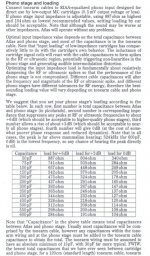
This Lyra cart loading is quite enlightening
Hi Sampler
As per my calculations, the "bass resistor" 65k should be 53600 but we must take in consideration that this 65k is parallel to the output impedance of the previous stage and may be also interacting with the input imp of the output buffer. That is why I did not propose any alteration there.
Anyway, using a 15k // 16k2 instead of 15k // 15k is enough to make a fairly good aproximation for optimal R18 (7793r), using the stock 40.8 and 13.6 caps.
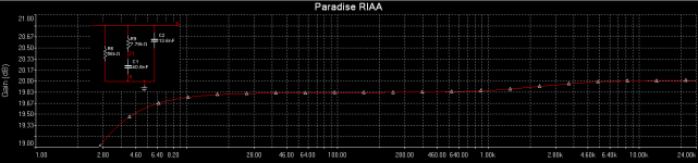
Yes... maybe it would need some picos in the 13.6nF (my target is 13.99) but that can be tweaked latter by hear if there is "subjectively" too much trebble. I found some resistance in oher threads regarding these adjustments because some claim 0.2dB difference is inaudible
As for R9, decreasing it´s value (with some megas in parallel) can also be done latter if needed. I prefer to call that resistor the "presence resistor" instead of "bass resistor" because it slides the curve up and down from 0 Hz to the upper midband.
As for R9, decreasing it´s value (with some megas in parallel) can also be done latter if needed. I prefer to call that resistor the "presence resistor" instead of "bass resistor" because it slides the curve up and down from 0 Hz to the upper midband.
Last edited:
Here is the official schematic.
Do i miss something here ? I can not see the 200 Ohm resistor.
Hi, yes thats the schematic the PCB is based on, with one exception / there is a 220Ohm resistor in series with C1a/C1b, for those of you who want to implement Neumann. Otherwise just put a wire instead, or a 0 Ohm resistor if you like.
The minimum transformer voltage is thus 25V ....
Maybe Hessener can comment on that (the temperature of the heatsink).
In my build I am using a 2x24V transformer with no problem, no-load voltage was 38V DC and loaded it was around 31V if my memory serves me well. I will measure the heatsink when I return, and some more...
Hi Joachim... the official schematic differs from the one I have and also from the boards inscriptions... R47 = 10 instead of 22 and R51 = 15 instead of 22... what values should I use.... My boards are almost finished
oops, sounds like the boards have the wrong values printed.... thanks for highlighting. I think I remember that there was some conversation around these resistors and that 10/22 was the final "verdict", so I must have changed them in the schematic but not on the PCB. Anyhow, maybe MiiB or Joachim can confirm so I can fix this bug, would be great!