if you go to batteries -- new fully charged NiCd -- good luck finding them (readily available over here.)
Why would you use nicd ?
Why would you use nicd ?
Lowest noise per volt, Nimh comes in second. See Hoffmann "Noise Measurements of Chemical Batteries"
Last edited:
Thank youLowest noise per volt, Nimh comes in second. See Hoffmann "Noise Measurements of Chemical Batteries"
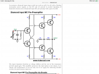
This is a version with a diamond input.
I like the Broskie version
")
Did you have a low inductance load right on the output of the capacitor multiplier? If not you should add a capacitor with a little bit of ESR but low inductance real close to it.
Please, always snub a cap multiplier.
Any inductance after a regulator or cap-multiplier is like putting on dirty underwear after a refreshing morning shower.
Zetex
another reason to have Horowitz & Hill, The Art of Electronics V3 on your bookshelf!
Zetex
Would you please suggest a model ?
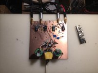
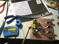
This time I have luck. The circuit in post 11082 worked right away.
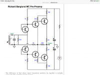
The only difference is that I use a conventional plus-minus supply.
That has a disadvantage. Input and output offset has to be trimmed.
I simply made the two supply voltages as similar as a could with a simple trimmer.
There is is a bit of hum. That partly comes from the mains transformer that is in board and partly from the PSSR that is not that great.
I have a solution for this that I will try now.
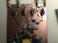
Attachments
ZTX851, 951
Very low Vcesat.... that means low Rcesat... very good
Do you know if they make a dual NPN/NPN and dual PNP/PNP version ?