Yes, I built one of Kean's buffers. That is a good buffer, high resolution, very accurate and does nothing other than buffer very nicely.OK, i build it tomorrow.
It doesn't seem to have an influence or signature of its own, and in that way, Kean's discrete buffer worked better than any of my chip buffers. The discrete took longer to build, but the project had completed much more quickly because it is so clean and doesn't color the sound, so that (in the long run) made it much easier to use than a chip.
There was a chip involved in the build, but that was the adjustable voltage regulator.

Last edited:
This is not a feedback buffer, so there is no way I can see to give it gain. Even if you did, the feedback network would likely cause parasitics to overwhelm the positive features of this circuit.
And, as one example of how this stage might be used, how about using this for the SSA frontend?
This circuit can be used as a transistor itself. Compared to a transistor it appears to have far higher transconductance; Rm will be pretty close to the degeneration resistor. You could use it in a high-linearity LTP; it may work better than a CFP LTP, I wonder.
It can also be seen as a self-biasing Diamond buffer or buffered driver. You can use a pair of these to drive the output stage of a BJT or FET amp. No need to fiddle with CCSs for the diamond drivers when they bias themselves and cancel distortion while they're at it.
Of course this is all at the cost of many extra solder joints, and you don't really need a supertransistor in many places to get good performance, just skilled design.
Making the input Ic 1/10 the output Ic improves stability by 10 times, which is why I did it. There are also other considerations like thermals and offset. Where is Hawksford's schematic?
Well, my simulations show thermal runaway. I didn't realize that thermal coupling with the inputs would add them to the error correction and so lose any protective effect they may have. So, I cross-coupled them instead. This way the thermal errors correct each other rather than trying to correct themselves and being thwarted by the EC.
The result is an output bias that depends much on supply voltage, so it needs at least zeners across the rails. That is in fact best since it needs inherent current limiting in case of thermal runaway while testing. This schematic should work. Use it along with the instructions in post 9269.
Also attached is a screenshot of my thermal simulation, for curiosity only.
PS. LTSpice says this thing has a BW of 265MHz!!!
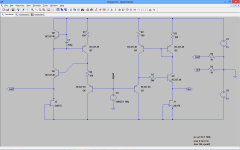
This is a part of the circuit Pioneer used in their MZ1 Amps of 1978, there probably was a patent involved.
Today I have built and tested this two buffer, and they work very well both of them.
But the asymmetric keantoken buffer was the best, the distortion is very low with 2vrms and 1k load, the distortion was only 0.0008 mainly 2º .
shunt Q8 with a 1000uF capacitor to desactivate the error correction loop the distortion is 0.038% , so the error correction works very well ,
Adding a capacitor like I have suggested in previous post in parallel with r4 thoes not work, and makes the circuit oscilate, is better to use c1. The circuit is stable without the cap anyway , so is your choice , to use it or not.
The other buffer needs a base resistor r7 to be stable.
I like the buffer asymmetric, but to have less distortion possible ,One must adjust R3 and this causes the voltage at the output to desviate from 0 volts , in the prototype the output voltage was 140mV, need to find a soluction for this.
but the keantoken circuit is a winner.
One thing that happens a lot, is simulating a circuit in ltspice and the circuit is stable but in reality is oscillating and some time in simulation is oscillating but in reality is stable.
beginning to suspect that is something wrong with my reality
Attachments
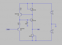
was trying to use R3 and R4 with 47R and the circuit begin to oscillate at 30Mhz .
To stop the oscillation 3 solutions worked.
a capacitor of 47pf between base and collector of Q5.
a 100ohms resistor in serie with the base of Q5.
or a 220pf capacitor between Q5 base and ground as picture.
EDIT:adding a snubber with 510R and 47pf at the input, as Keantoken suggested, also worked.
To stop the oscillation 3 solutions worked.
a capacitor of 47pf between base and collector of Q5.
a 100ohms resistor in serie with the base of Q5.
or a 220pf capacitor between Q5 base and ground as picture.
EDIT:adding a snubber with 510R and 47pf at the input, as Keantoken suggested, also worked.
Attachments
Last edited:
I prefer the input snubber as compensation because it does not affect the error correction.
Do use the schematics in post 9271 or 9276. The schematic in post 9271 has been built and tested and verified by at least 2 people, me and Dan. That way you will not be both confused and a guinea pig. Post 9276 hasn't been built and tested and although it should work, it will ultimately have more distortion. I simply provided it since you wanted a symmetrical version.
Sergio is following my tracks so don't consider his experiments to be improvements or suggestions unless he says so, I just see it as him investigating. I think he should try the circuit in post 9261 since it addresses more distortion mechanisms. It is NOT the same as the circuit without the 1k resistors and caps.
Last edited:
Joachim, how about this? This version should have the best performance.
Decoupling is not critical as long as it is there. If it affects the sound then I would encourage you to use what you prefer. I avoid the use of film decoupling <470nF along with low-ESR lytics because the rail resonance may provoke oscillation.
I would like to know THD numbers before an after trimming, if possible, so I could put it on the schematic. Dan has told me sternly the circuit sounds excellent at most trimmer settings. I think trimming adds some nuance but it's not very much.
Using BC337-40 as the outputs I think sounds better mostly, but if/when you do that you will need to do step 2 of the trimming procedure because the Vbe will be different.
Attachments
Last edited: