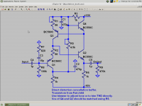
It doesn't seem you guys realize this, but the Vbe nonlinearities in this EC topology cancel. It is essentially the Tringlotron, except input and output are able to share a common ground. I came up with this independently many months ago and have done several experiments with this topology since it is extremely fast and should allow improvement in linearity of various circuits by canceling Vbe distortion directly rather than hoping to attenuate it to a satisfying number of zeros. As it turns out, BC5xx/BC3x7-40 have close enough Vbe that they should be matched enough to do very well in this topology.
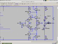
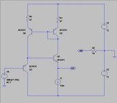
Instead of using two PNP's for the mirror, it is better to use an NPN and PNP, that way the complimentary parts' differences in matching are also cancelled. I have built this circuit several times and it works as expected. By trimming the match you can get a positive or negative 2nd harmonic. This gives very subtle acoustic effects. You can get very visceral bass this way.
I have tried NXP BC8xxC duals for this but surprisingly, they don't actually seem to achieve better thermal coupling then two TO92's. This frustrated me, besides the attempt to p-p solder the SMD package.
The speed of this configuration makes it useful as a very fast buffer, and so naturally it could find application in linear regulators, amplifier stages and so on. One problem is that input resistance is negative at at high frequencies, and output resistance may be negative, which is what the 4.7R is for.
So I regard this as an improvement on the Tringlotron.
The biasing scheme keeps the temp of the transistors roughly equal; coupling TO92 transistors really doesn't help much with the thermal differential.
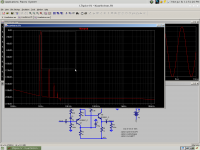
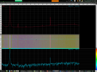
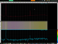
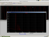
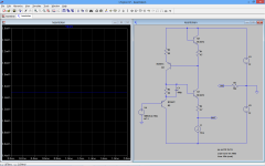
Also attached are FFT plots with and without the buffer. I don't trust these results, because the 2nd harmonics did not respond to trimming at all. I think something else was causing the 2nd harmonic and the buffer's actual H2 was obscured by it. I seem to remember getting -90db with some other configuration. Still, we know that THD is at least that good.
Instead of using two PNP's for the mirror, it is better to use an NPN and PNP, that way the complimentary parts' differences in matching are also cancelled. I have built this circuit several times and it works as expected. By trimming the match you can get a positive or negative 2nd harmonic. This gives very subtle acoustic effects. You can get very visceral bass this way.
I have tried NXP BC8xxC duals for this but surprisingly, they don't actually seem to achieve better thermal coupling then two TO92's. This frustrated me, besides the attempt to p-p solder the SMD package.
The speed of this configuration makes it useful as a very fast buffer, and so naturally it could find application in linear regulators, amplifier stages and so on. One problem is that input resistance is negative at at high frequencies, and output resistance may be negative, which is what the 4.7R is for.
So I regard this as an improvement on the Tringlotron.
The biasing scheme keeps the temp of the transistors roughly equal; coupling TO92 transistors really doesn't help much with the thermal differential.
Also attached are FFT plots with and without the buffer. I don't trust these results, because the 2nd harmonics did not respond to trimming at all. I think something else was causing the 2nd harmonic and the buffer's actual H2 was obscured by it. I seem to remember getting -90db with some other configuration. Still, we know that THD is at least that good.
Attachments
From Mr Evil's page:
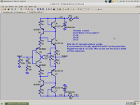
This shows a common misconception about how this kind of stage works. If it really worked this way, there would be no distortion reduction at all because the Vbe error would not be canceled, only the load error. If the load is a perfect resistor, then load nonlinearity is not the problem we are trying to correct.
The buffer works because it uses a transistor to copy the nonlinearity of the output transistor and then applies the correction. Correction of the sort Mr Evil describes reduces output resistance, but does not reduce the error in the output resistance.
I originally considered this feedforward error correction but I have not actually studied it much so there might be some subtle distinction I'm missing.
I don't think error correction or most things topological really are confusing, if understood from a topological, nuts and bolts way. All the cerebral abstraction going on seems to give the impression that these things are complex and abstract. I think this is just a red herring.
The input voltage to this source-follower is then the difference between the diamond buffer's input and output voltages. This causes the bias current to increase when the load increases, helping to reduce distortion.
This shows a common misconception about how this kind of stage works. If it really worked this way, there would be no distortion reduction at all because the Vbe error would not be canceled, only the load error. If the load is a perfect resistor, then load nonlinearity is not the problem we are trying to correct.
The buffer works because it uses a transistor to copy the nonlinearity of the output transistor and then applies the correction. Correction of the sort Mr Evil describes reduces output resistance, but does not reduce the error in the output resistance.
I originally considered this feedforward error correction but I have not actually studied it much so there might be some subtle distinction I'm missing.
I don't think error correction or most things topological really are confusing, if understood from a topological, nuts and bolts way. All the cerebral abstraction going on seems to give the impression that these things are complex and abstract. I think this is just a red herring.
I wanted to post this after I had explored this circuit much more fully. There are still many things to try and real-world optimizations that need to be tried.
Log-conformance BJTs (LM194?) might be best. However my complimentary current mirror should solve this problem. Ib, Early and tempco are the major sources of error. Ib distortion is potentially benign because Ib is proportional to Ic and so is Gm - however this requires a lopsided trimming and we want the circuit not to depend on Hfe. Early effect and tempco need to be solved together with cascodes.
Even hand-matched transistors may have variances in Rb and Early effect. Anything that affects log conformance. It is best to first choose a transistor and manufacturer known for inherently excellent matching, and then match from a similar batch if those are not good enough. However I think for modern standards anyways, Fairchild BC5xxC are excellent out of the box.
I have tried the BC3x7-40 as well and while they seem to sound better, imaging seems to suffer a bit. I think my system has serious imaging problems so I would advise you to come to your own conclusions. Theoretically, the BC3x7-40 are ideal because of low Rb and high thermal inertia. I may do measurements with them and see if that changes the H2.
A good performance metric for single-ended EC circuits like this is H3. While you can always tune out H2 even in non-EC circuits, H3 shows how good the null really is. One route to improving such a circuit then is to make topology changes until H3 is lowest - then you know there is a good inherent null. In this regard this circuit should be one of the best. More inherently matched transistors as above should also reduce H3.
I'm guessing the equivalent metric for vertically symmetric circuits would be H6.
I should add that thermal coupling doesn't help much when the CAUSE of thermal difference is the dissipation of the transistors themselves - if the cause is instead a mischievous imp blowing on one transistor, thermal coupling should help greatly.
Last edited:
I don't care for the coupling caps either. I wouldn't leave them out of a schematic however. Output offset is generally below 100mV.
There is this. I haven't explored it much as I tried to optimize the first version before that. I haven't built it. Furthermore, this one may have trouble turning on. Input and output transistors should be coupled to prevent thermal runaway. I don't know if that's actually possible but it may be for this circuit.
Ideally dissipation would be equalized for all transistors, but in this case the thermal differential must be used to bias it into class A. Evidently it was intended to be a headphone buffer, but the circuit will probably do extremely well as a line buffer.
I can come up with all sorts of stuff for those who ask. I try to make the designs I post consolidations of a wide array of experimentation. I could post endless variations on this general circuit for various purposes, like the Kmultipliers. If you guys give me a list of criteria I might have a go at it.
Attachments
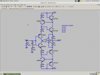
That would be great. Since you seem interested I've modified this one to be more likely to work well the first time. While this version is symmetrical, it is not dissipation-matched. so while the H2 of each half may (or may not) cancel, the 3rd harmonic will not and to that degree neither will the 6th harmonic. The single-ended version is more likely to have a more monotonic spectrum for this reason, and the same logic applies pretty much to most other circuits. Still, the distortion should be very low.
First measure Vbe of several kinds of each type. In my experience they are usually within 1mV. If they are within 3mV or so, don't bother matching.
( 60mV + Vbe(Q1-Q3)) / 1mA = R4=R6
Do this for both halves. Adjust R8 for 10mA output bias. The finished circuit should have 1mA through the inputs, 10mA through the outputs.
When and while powered on, monitor bias to make sure it doesn't runaway. The circuit may fail to start. If so, jump start it by touching a 10k resistor from the output to one of the rails. If it oscillates, increase input decoupling.
Attachments
Nice circuit keantoken . At a first glance ,it seems that adding a small cap in parallel with R2 will compensate the error correction loop, have you try that?
The circuit I reefer is at post #9261.
You would be right, if that were the problem that needed compensated. This circuit is like regulators. It is rock solid until you do something funny with it. The input RC is closer to the source of the problem. I've been using this circuit for a while without any trouble with oscillation, but this is in an idealized bench environment.
Thermal gain is proportional to Vce. Q1 has higher Vce so the current sensing transistor doesn't share thermal effects with the output and so won't correct for them. This version will have much worse thermal bias behavior (if used symmetrically), because despite this the 4.7R is canceled so there is nothing to keep the thermal gain at bay.
Last edited:
Making the input Ic 1/10 the output Ic improves stability by 10 times, which is why I did it. There are also other considerations like thermals and offset. Where is Hawksford's schematic?
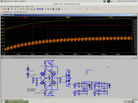
Well, my simulations show thermal runaway. I didn't realize that thermal coupling with the inputs would add them to the error correction and so lose any protective effect they may have. So, I cross-coupled them instead. This way the thermal errors correct each other rather than trying to correct themselves and being thwarted by the EC.
The result is an output bias that depends much on supply voltage, so it needs at least zeners across the rails. That is in fact best since it needs inherent current limiting in case of thermal runaway while testing. This schematic should work. Use it along with the instructions in post 9269.
Also attached is a screenshot of my thermal simulation, for curiosity only.
PS. LTSpice says this thing has a BW of 265MHz!!!
Attachments
The equation in post 9269 SHOULD be:
( 60mV + Veb(Q7)-Vbe(Q5) ) / 1mA = R6 = R5
Vbe is measured before the transistors are soldered into anything. Perform the same for the other half. The circuit will probably work fine without this, but it will keep batch variances from making unexpected differences in the circuit.
( 60mV + Veb(Q7)-Vbe(Q5) ) / 1mA = R6 = R5
Vbe is measured before the transistors are soldered into anything. Perform the same for the other half. The circuit will probably work fine without this, but it will keep batch variances from making unexpected differences in the circuit.