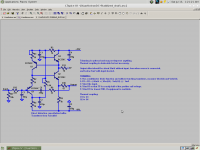
The voltage at the circuit's "ground" needs to be halfway between the rails. Something like this.
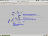
EDIT: Better schematic.
Thank you, so you use a voltage divider to set the bias in the input.... it would take me too long to think about that.
What should I adjust to use it with +35v - 0v ?
Thank you, so you use a voltage divider to set the bias in the input.... it would take me too long to think about that.
What should I adjust to use it with +35v - 0v ?
Ricardo, there is no need to adjust anything.
What was the load and the voltage ?
Input voltage was the max my soundcard would tolerate, which I think is +-1V. The circuit was unloaded per se, but it would take at least a 5k load to be much worse than the 1k resistor already loading the output.
Ricardo, there is no need to adjust anything.
Do you know that for sure? Without changing anything, that gets us 17.5mA bias current at 8.75V. That's 150mW. 3 times higher than the 50mW under normal conditions. That's 57C rather than 37C. The circuit will be 3 times more sensitive to thermal imbalance. The old bias scheme will not apply anymore and operating currents will need to be redefined. Furthermore, the BC560C/550C have relatively high Rb, which begins to dominate at high currents, not to mention Ib changes. You are encouraging him to build a circuit that has not been tested and saying it will be equivalent to what we have already tested, which is arguable at best. If RCruz wants to be a guinea pig, that's cool, but lets be straightforward. This circuit hasn't been tested that much that I can see.
As long as you have tested it.
That said, .0025% into 1k is a bit large considering the potential of this circuit. I didn't need an SK170 to get 20db less. I would say if RCruz wants to operate at over 20V and over 10mA, he is testing a new version of the circuit. I would think he wants to build what has been proven to work best at the moment.
That said, .0025% into 1k is a bit large considering the potential of this circuit. I didn't need an SK170 to get 20db less. I would say if RCruz wants to operate at over 20V and over 10mA, he is testing a new version of the circuit. I would think he wants to build what has been proven to work best at the moment.
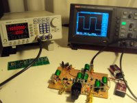
I have build one channel of the buffer now and it worked right away.
At the moment i use it without trimming. Voltage at the test point is 5.7V and i use 9,3V batteries. That shows in slight asymmetric clipping, the positive voltage clipping first.
Instead of 56 Ohms i am using 47 Ohms because i had them.
DC offset at the output is 1.5mV. Offset at the input only loaded with 100kOhm is 75mV.
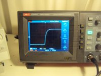
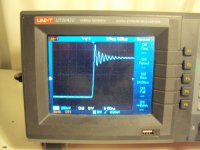
That goes down to under 1mV when i connect my generator that has 50Ohm output impedance. The circuit had considerable overshot on a square wave, even with snubber.
I have then added a 220 Ohm, 150pF lowpass. Now it looks fine.
I will measure now distortion.
At the moment i use it without trimming. Voltage at the test point is 5.7V and i use 9,3V batteries. That shows in slight asymmetric clipping, the positive voltage clipping first.
Instead of 56 Ohms i am using 47 Ohms because i had them.
DC offset at the output is 1.5mV. Offset at the input only loaded with 100kOhm is 75mV.
That goes down to under 1mV when i connect my generator that has 50Ohm output impedance. The circuit had considerable overshot on a square wave, even with snubber.
I have then added a 220 Ohm, 150pF lowpass. Now it looks fine.
I will measure now distortion.
I would not add the jfet CCS until after I knew I had hit the limit of the original circuit, if I needed even less THD. It may help if there are quality control problems but that does not seem to be the case.
EDIT: can you say how much overshoot there is? IE 20% or 5%?
EDIT: can you say how much overshoot there is? IE 20% or 5%?
Last edited:
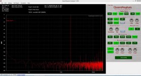
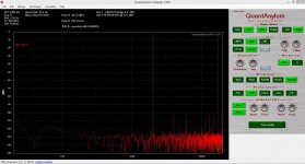
I measured the input signal with left channel, output signal with right channel. Then I use Baudline to subtract one from the other. It gets rid of lots of stuff, so the noise floor is surprisingly low.
For this soundcard at least, left and right channels are very well-matched.
For this soundcard at least, left and right channels are very well-matched.
Attachments
Now is time to say good bye , I am sorry but I just don't like bad vibes. I just try to help.
That is seriously not my intention. You are very gifted and I'm very interested in your work. Your Jfet CCS is a great idea. It does what is intended. I hope the points I've made are helpful, when any poor vibes are tossed in the garbage where they belong.
I'm sorry if I have a condescending tone. I acknowledge it as a personal issue. At the same time no one but me can make it different, and changing oneself is not easy. Please be patient with me. At the moment I am overwhelmed with horrible sleep hours and a bunch of competing projects.
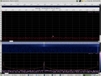
Here is the square wave response with and without the input filter plus closeups.
Joachim, I don't like to see the ringing but it is actually a natural consequence of the output inductance of the buffer resonating with capacitance at the output. All amps do this, without some sort of snubbing scheme. That's what compensation is basically, the trick is to find the most benign snubbing scheme. I've spent the last few years trying to understand this sort of thing.
This is what I came up with. It should be phase-linear with up to 1nF at the output, enough for any signal cable hopefully (lol!). There should be no ringing on small-signal square waves, which is where the music is.
I haven't been able to test it but I can't find a reason why it won't work. I think I might try it tomorrow if the stars align.
Attachments
I wish I could delete that last schematic. That actually applies to the BC337-40 version, which is easier to stabilize.
I only recently learned about this specific kind of compensation so when I decided to post this buffer, I hadn't thought to stabilize it this way. To try not to waste any more of your time, here is a convenient schematic. You magically have already installed the 220R/150p filter. All you need to do is put in C6 and R9. That hopefully will stop the ringing, rather than just putting it in quarantine.
I only recently learned about this specific kind of compensation so when I decided to post this buffer, I hadn't thought to stabilize it this way. To try not to waste any more of your time, here is a convenient schematic. You magically have already installed the 220R/150p filter. All you need to do is put in C6 and R9. That hopefully will stop the ringing, rather than just putting it in quarantine.