Hello chipco3434,
C001 and C002 are the to make sure no high frequency noise gets into the filter, and C200 & C500 are the to ensure stability.
C800 & C900 are the main supply caps. The filter will work without the components, but I suggest you C001, C002, C800 and C900 eventually.
Sorry I can be of no help regarding the opamp.
Hope this helps you.
\Jens
chipco3434
C001-C002, I used what I had available, 39pF. A note to discrete op-amp users. The C800-C900 supply filter caps will have to be very narrow or go on the underside of the board in order to fit properly because the discrete input buffer gets in the way. Lucky for me I didn't install them until I had assembled the discrete op-amps.
A good part number from Mouser for the 8 pin DIP socket would be 575-113308. Those right angle headers are expensive so if you are not going to be exchanging op-amps it sure would save you a few dollars not having to buy sockets and/or headers.
AS far as C200- C500 I had a similar question and I believe MOAMPS thoughts were compensation would only be needed for input and output discrete op-amps and not for the filter op-amps. If you take a look at MOAMPS work this is how it is setup.
BDP
3. I am unable to identify the components associated with C001 and C002, C200 & C500, and C800 & C900. I could use the values and even better, some part numbers.
C001-C002, I used what I had available, 39pF. A note to discrete op-amp users. The C800-C900 supply filter caps will have to be very narrow or go on the underside of the board in order to fit properly because the discrete input buffer gets in the way. Lucky for me I didn't install them until I had assembled the discrete op-amps.
A good part number from Mouser for the 8 pin DIP socket would be 575-113308. Those right angle headers are expensive so if you are not going to be exchanging op-amps it sure would save you a few dollars not having to buy sockets and/or headers.
AS far as C200- C500 I had a similar question and I believe MOAMPS thoughts were compensation would only be needed for input and output discrete op-amps and not for the filter op-amps. If you take a look at MOAMPS work this is how it is setup.
BDP
A wall wart is actually a great idea as it keeps the transformer far away from your sensitive circuit. You need an AC wart though.
Here is a perfect supply. You can improve it in a number of ways, but for a novice, KISS is a good approach IMHO.
http://sound.westhost.com/project05.htm
Here is a perfect supply. You can improve it in a number of ways, but for a novice, KISS is a good approach IMHO.
http://sound.westhost.com/project05.htm
The supply voltage needed for the module is greatly depending on what opamps you use.
Generally I suggest that you use +- 15V, but the filter will work on +-12V also.
Each filter will consume maximum 100mA so a LM78/7915 should be ok for a 10 board scenario.
I hope this answers any questions about power supply for the board.
I will try to get time to update the manual, with a power supply schematic for the filters and other information that might come in handy during the build process.
\Jens
Power supply voltage
As an extension of the discussion regarding power supplies, has anyone considered using voltages above 15V for the discrete op amp?
Mr. Pass says in his DIY Op-Amp paper that the sk389 works well with 32V. I felt from my reading that his preference was for higher voltage.
The article is available for download from his Legacy Projects here: http://www.passdiy.com/legacy.htm
I know it's off topic, but I can't help myself, I have to post it
An engineer died and ended up in Hell. He was not pleased with the level of comfort in Hell, and began to redesign and build improvements. After a while, they had toilets that flush, air conditioning, and escalators. Everyone grew very fond of him. One day God called to Satan to mock him, "So, how's it going down there in Hell?" Satan replied, "Hey, things are great. We've got air conditioning and flush toilets and escalators, and there's no telling what this engineer is going to come up with next."
God was surprised, "What? You've got an engineer? That's a mistake. He should never have gotten down there in the first place. Send him back up here."
"No way," replied Satan. "I like having an engineer, and I'm keeping him." God threatened, "Send him back up here now or I'll sue!" Satan laughed and answered, "Yeah, right. And just where are YOU going to get a lawyer?"
\Jens
Excellent joke Jens...
To Ed: maybe I give the short answer re: supply voltages far above 15V.
In short it's not that simple. The circuit values and components were chosen with a certain supply range in mind. 12V or 15V or maybe 18V won't change the circuit's behavior much. Large deviations from this figure (such as 32V) means, you would at least have to recalculate the bias currents to check if they're still in the optimal range with the original resistor values. A 32V supply may also exceed breakdown voltages for some of the other transistors (though the 2SK389 may take it).
Markus
Screw for discrete op amp
I visited several sources with boards in hand, looking for screws to connect discrete op amp boards together. This is what I found necessary:
#2-56 x 5/8"long.
Sincere apologies to our metric friends.
McMaster-Carr has them available. Oval head, Stainless Steel
screw pn: 91802A083
nut pn: 91841A003
MBK: Thanks for your "caution" about other devices on the boards not withstanding increased voltages. Changing resistors for bias adjustment would be (for me) an acceptable part of finding the "sweet spot" in the performance of a circuit. At this time I will provide +/- 15V. My interest is in future tweaking of the op-amp.
Grounding
Hello,
I have a question about the proper way to attach the grounding when using a seperate external power supply and seperate x-over chassis.
Should each ground from the MOX boards return to the separate power supply chassis ground or would returning all grounds to a common point at either the input or output grounds on the x-over chassis be best?
I want to build a 2 channel bipolar supply that will output a regulated +\- 36 volts. This could then be used for other projects or changes in the future and then do further regulation for the specific circuits. So, for the MOX x-over I would use regulators +\- 15 to 18 volts in the X-over chassis and have the +\- regulated 36 volts feeding the x-over chassis.
Thanks in advance for any replies. ( maybe Mo-amps will reply )")
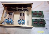
X-over boards are stuffed, discrete op-amps are assembled. Purchased two 20 series chassis from Par-metals (Nice chassis). Working on the power supplies.
How are others coming along on their x-overs. Haven't heard much for awhile???
BDP
Hello,
I have a question about the proper way to attach the grounding when using a seperate external power supply and seperate x-over chassis.
Should each ground from the MOX boards return to the separate power supply chassis ground or would returning all grounds to a common point at either the input or output grounds on the x-over chassis be best?
I want to build a 2 channel bipolar supply that will output a regulated +\- 36 volts. This could then be used for other projects or changes in the future and then do further regulation for the specific circuits. So, for the MOX x-over I would use regulators +\- 15 to 18 volts in the X-over chassis and have the +\- regulated 36 volts feeding the x-over chassis.
Thanks in advance for any replies. ( maybe Mo-amps will reply )
X-over boards are stuffed, discrete op-amps are assembled. Purchased two 20 series chassis from Par-metals (Nice chassis). Working on the power supplies.
How are others coming along on their x-overs. Haven't heard much for awhile???
BDP
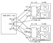
Hi BDP,
I think it would be best to use one power supply for each crossover channel. Experience has taught me that grounding loops can be very tricky business, especially when it comes to a bit more complex power supply schemes like the one you would like to implement.
I myself am not so sure that this is a good way to go but if that's what you want, see the block diagram in the attachment below that shows you how I would do the grounding if I really had to. The basic idea is that the power grounds and signal grounds meet in only one point, which is the star point of the main power supply. The power grounds and signal grounds of other equipment that you may choose to connect to the main power supply should also be isolated in this way. In practice, this means that power supply cables from the main PS to each piece of equipment should consist of 4 wires (for +VC, -VE, power ground and signal ground). I hope this helps.
Regards,
Milan
Attachments
Thanks moamps for the reply,
I will be using one power supply for each channel. Both will be housed together in a separate enclosure from the x-over boards. I will only be powering the MOX boards. If I put 4 MOX boards in one enclosure then there is no room for transformers. This way I get some isolation between the transformers and the X-over boards. I hope to keep the power and ground wires as short as possible. Six to eight inches. I want a more flexible supply so I can power experimental circuits in the future without having to build a new quality supply again.
Looking at some pictures of the XVR X-over I see the power is attached by a DB-25 connector. Maybe it is used because of all the returning grounds to the power supply??
What power supply arrangement would you implement for the MOX design?
BDP
I will be using one power supply for each channel. Both will be housed together in a separate enclosure from the x-over boards. I will only be powering the MOX boards. If I put 4 MOX boards in one enclosure then there is no room for transformers. This way I get some isolation between the transformers and the X-over boards. I hope to keep the power and ground wires as short as possible. Six to eight inches. I want a more flexible supply so I can power experimental circuits in the future without having to build a new quality supply again.
Looking at some pictures of the XVR X-over I see the power is attached by a DB-25 connector. Maybe it is used because of all the returning grounds to the power supply??
I myself am not so sure that this is a good way to go but if that's what you want, see the block diagram in the attachment below that shows you how I would do the grounding if I really had to.
What power supply arrangement would you implement for the MOX design?
BDP
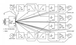
This sounds just fine.BDP said:I will be using one power supply for each channel. Both will be housed together in a separate enclosure from the x-over boards. I will only be powering the MOX boards. If I put 4 MOX boards in one enclosure then there is no room for transformers. This way I get some isolation between the transformers and the X-over boards. I hope to keep the power and ground wires as short as possible. Six to eight inches.
I'm not sure. It's possible that NP uses a couple of pins for one signal connection. DB connectors have very good and reliable characteristics.Looking at some pictures of the XVR X-over I see the power is attached by a DB-25 connector. Maybe it is used because of all the returning grounds to the power supply??
What power supply arrangement would you implement for the MOX design?
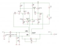
I built my last crossover using the block schematic in the picture below.
Regards,
Milan
Attachments
I have tried to change the opamp circuit around a bit. The main reason for attempting this would be because I have recently completed a nice power supply that has 32V rails and I like all the op-amp boards that I got.
I recently downloaded the SIMetrix program which helps give a general idea of how a circuit will behave when changing values.
Along with reading the "DIY op amps" article by Mr. Pass it becomes easy to adjust the bias values, and this is all that is really needed to get something working with a different supply.
I have changed the output follower to ZVP3310a and the current source bipolar's to mpa18 (mpsa42 is very similar). I optimized the current through the 2sk389 to 4ma total shared evenly and 10ma through the follower. The bottom is just an input buffer with 0db gain to test the opamp.
I haven't built this yet but plan to. The circuit is the same and nothing has really changed so I don't foresee any problems.
-dave
Attachments
With the supply rails at +/- 32 volts R3 will have to dissipate 400 mW. Your resistors should be about double or so the wattage. The size would be getting rather large for the boards. You might try increasing the resistance to reduce the dissipation. A pot. in the drain used to adjust for variations between zvp3310's would be nice also, but at unity gain might not be needed.
BDP
BDP
- Status
- This old topic is closed. If you want to reopen this topic, contact a moderator using the "Report Post" button.
- Home
- Amplifiers
- Solid State
- MOX builder’s thread