kepa1 said:
this is all new to me so before ordering i was wondering if you would publish, apart from the schematics, some sort of manual for component placing and other recommandations,
Tiroth,
Likewise, I would apreciate any further info.
Regards, APK
pinkmouse,
That's a good idea. There is no problem with the topology, since the inverting input is already "free" for use as a balanced input. I'll see if I can squeeze some additional pads in to accommadate the extra resistors and inputs.
kepa1+APK,
I will be creating a stuffing guide. I'll post some more info on my site tonight.
Order form
http://tiroth.brinkster.net/mox_order2.html
Banned
Joined 2002
tiroth said:Coulomb,
I'm guessing you are referring specifically to the discrete opamp--that design always operates in Class A by default.
Doh!
Thanks for the quick response.
Anthony
I have partially recovered my site from backups. I will work next on recovering the images in the opamp assembly guide and writing the the MOXlite assembly manual. Jens has been a big help with this -- thanks Jens!
Please do not be alarmed when the order form redirects to this page:
http://www.anidian.com/audio/construct/mox_order.shtml
Please do not be alarmed when the order form redirects to this page:
http://www.anidian.com/audio/construct/mox_order.shtml
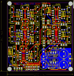
Tweaked layout, including a total of 4 potential inverting inputs for bass management usage. Other changes included routing improvements and overlay changes for readability.
http://www.anidian.com/doc/moxlite_v21_board.pdf
http://www.anidian.com/doc/moxlite_v21_board.pdf
tiroth said:Tweaked layout, including a total of 4 potential inverting inputs for bass management usage. Other changes included routing improvements and overlay changes for readability.
BROKEN LINK REMOVED
Hummm Page Cannot be found.
Anthony
Size: The boards are 3.09"x2.9" (79mmx74mm)
On-board pots: I have added space for a 3-terminal pot on each channel. There is limited functionality from this though--this will work great if you have the amp in the same box, but it won't be useful if you need a line driver, because there is no buffer after the pot.
Balanced out: I'm sorry, but this board just isn't going to support balanced out. Using normal opamps the size of the board would increase almost 100%, and even using something like DRV134 it would be 50%. All is not lost, though--pseudo-balanced works fairly well in most cases, especially if you have a high quality receiver.
Of course, one could always add buffers or balanced drivers on a small protoboard.
Here is the new layout. The ground plane is moved because it is a pain to keep ripping it up for each change.
http://www.anidian.com/doc/moxlite_v22_board.pdf
Attachments
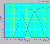
Here are the actual measurements from the prototypes. This is for a real set of active loudspeakers
Low pass: 320Hz, Q=0.5
Band pass: 320-3200Hz, Q=0.5
High pass: 1600Hz, Q=0.5
The red trace shows the high pass output, the blue trace shows a parametric notch filter centered at 12kHz, gain -3dB, Q=4.
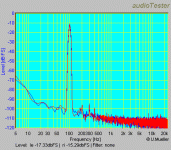
I can see from the HF measurement that I need to reduce the ground fill a bit around the HP section. I thought that simply moving to a single-side fill would be enough, but I can see there is still a little too much stray capacitance.
Attachments
Tyler,
Nice work
What's the problem with the groundplane? does the measurement not match the calculated response?
I did some experiments with my filter one board and found that the calculated response matched the measured nicely.
Please explain further
\Jens
EDIT: added image
Nice work
What's the problem with the groundplane? does the measurement not match the calculated response?
I did some experiments with my filter one board and found that the calculated response matched the measured nicely.
Please explain further
\Jens
EDIT: added image
An externally hosted image should be here but it was not working when we last tested it.
- Status
- This old topic is closed. If you want to reopen this topic, contact a moderator using the "Report Post" button.
- Home
- Group Buys
- MOX active crossover buy


