Are there any earlier examples of feedback to a pentode or tetrode grid circuit?
O. H. Schade also used a curve tracer to show that plate-grid feedback results in a triode-like curve.
In his paper, he uses a simplified circuit to illustrate the principle.
Does it really matter as long as the plate signal subtracts arithmetically from the grid signal?
Was not feedback already used then? Was not it shown to linearize transfer functions?
I think not. It's all just local feedback of one sort or another. Heck, Blumlein was using plate-grid local feedback before 1934.The question was, either to attribute any local feedback in output stage from anode to control grid to Schade, or not.
Last edited:
No.
In the original Schade article interstage transformer was used, and feedback was applied to the side of the secondary opposite to the one that was connected to the grid. It was applied in series with input signal.
On your picture in both cases feedbacks are applied in parallel with input signal.
Exactly. I asked the same question some time ago
IMHO, this whole Schade thing is overrated and nothing new under the sun. Just a fancy name.
When applied in parallel this decreases the input resistance immensely. Now when a pentode is used as driver the whole concept has nothing to do with distortion reduction anymore.
Also, cherry picking one particular example of feedback and giving it a special name just makes it more difficult for others to discuss circuits. Now they have to look up what 'Schade feedback' means (which might be difficult since it doesn't exist outside this forum), whereas 'local feedback' or 'plate-grid feedback' are general terms that are widely known.
Was not feedback already used then? Was not it shown to linearize transfer functions?
Yes, feedback was already developed 11 years before, as developed by Harold S. Black in 1927.
WPI - Transformations: Accentuating the negative
see also the same author in "Electrical Engineering" 53:114 1934, if this is available anywhere.
The important thing is that plate to grid feedback in the output stage, when driven from a high impedance driver (pentode) consistently produces triode like behaviour and much lower output impedance.
Its just a travesty that off the two common implementations out there the RH (Kitic) and the Tabor (Pimm), it is the RH which has gained popularity. A shame because it makes such a bad job of it. I suppose the Baby Huey is out there to show how it can be esily done to great good effect.
Shoog
Its just a travesty that off the two common implementations out there the RH (Kitic) and the Tabor (Pimm), it is the RH which has gained popularity. A shame because it makes such a bad job of it. I suppose the Baby Huey is out there to show how it can be esily done to great good effect.
Shoog
Hey SY,
No, that one isn´t a typical Schade as RCA have added a second feedback loop over two stages to the cathode of the driver. The beauty of Schade is just the local feedback.
If you want to see a modern version, NPs Zen is done exactly right. http://www.diyaudio.com/forums/pass-labs/144105-o-h-schade-1938-meets-mosfet.html
So the perfectly ordinary anode-follower feedback, which make the output stage act more like an opamp than a triode and increases driver stage distortion, was not what Schade did anyway?
I think we need a Bloggs circuit: Mr. Bloggs didn't invent it, and it doesn't do what everyone claims, but it could be the next fashion statement in audio. People who haven't heard of it, or doubt its claims, will automatically show themselves not to be true audiophiles. The fact that no textbook mentions it just shows how useless textbooks are.
I think we need a Bloggs circuit: Mr. Bloggs didn't invent it, and it doesn't do what everyone claims, but it could be the next fashion statement in audio. People who haven't heard of it, or doubt its claims, will automatically show themselves not to be true audiophiles. The fact that no textbook mentions it just shows how useless textbooks are.
So the perfectly ordinary anode-follower feedback, which make the output stage act more like an opamp than a triode and increases driver stage distortion, was not what Schade did anyway?
I think we need a Bloggs circuit: Mr. Bloggs didn't invent it, and it doesn't do what everyone claims, but it could be the next fashion statement in audio. People who haven't heard of it, or doubt its claims, will automatically show themselves not to be true audiophiles. The fact that no textbook mentions it just shows how useless textbooks are.
Not a fan I take it.
I always tend to call it plate to grid feedback - since that is what it is.
Shoog
Lars, didn't mean to be impure, just showing the output plate to pentode driver plate feedback connection used as a rational part of a set of tools to achieve a linear, stable power amp with good efficiency for the genus. There are several classic tube power amp designs out there worthy of complete analysis (e.g., 5-20, Williamson, Macintosh, Citation), and the RCA is one of them. Hmmm, might be an interesting project...
DF96, Don´t understand waht you mean about "and increases driver stage distortion".
What Schade found was that a pentode/tetrode with (local) anodefollower got triodelike characteristics. What attracts me is that you this way get triode characteristics and tetrode effiency.
This is the only commercial example I have found that exactly follows Schades paper:
http://www.hammondmfg.com/pdf/Dia_1229B.pdf
SY,
Didn´t RCA publish a 20W 6V6 with close to the same topology? Clearly RCA was on the right way when adding local feedback before the OPT and not over it.
Shoog,
Good idea to call it plate to grid feedback. This way we could end this discussion.
Last edited:
The circuit which most people call 'Schade' significantly reduces the input impedance of the output stage. This increases driver distortion, if the driver is a triode.revintage said:DF96, Don´t understand waht you mean about "and increases driver stage distortion".
We could call this circuit 'plate/anode to grid feedback', but it already has a perfectly good name: anode follower. Why not stick with the established textbook name for this circuit, rather than invent new names?revintage said:Good idea to call it plate to grid feedback. This way we could end this discussion.
That is why all those here who understand the circuit consistently argue against the misapplication of a triode as a driver.The circuit which most people call 'Schade' significantly reduces the input impedance of the output stage. This increases driver distortion, if the driver is a triode.
We have the unfortunate situation that the disciples of Kitic's RH amps vehemently maintain that they prefer the higher distortion triode version over a properly implemented pentode version - you give up hope for sanity.
It seems that many out there still believe the benefit of valves is in higher distortion

Shoog
Hey DF96,
Do you find anything positive with the "Schade"?
Seems you haven´t noticed that for a long time "plate to grid feedback" has been used here. AFAIK there are no textbooks that covers this particular use of "anode followers". This is 2012, maybe time to write new textbooks.
Do you find anything positive with the "Schade"
?Seems you haven´t noticed that for a long time "plate to grid feedback" has been used here. AFAIK there are no textbooks that covers this particular use of "anode followers". This is 2012, maybe time to write new textbooks.
Anode follower seems a suitable enough name if "Schade" is causing confusion.
And while it gives triode like curves, they are not quite the same as real triode curves. The neg. feedback is "linear" (resistive, but see below) for the anode follower, while the triode has non-linear feedback. In theory, the triode's finite nonlinear feedback could completely linearize its response (at least for constant current) if the grid and plate had the exact same characteristics (which unfortunately they don't due to proximity effects at g1).
Putting the shunt neg Fdbk to the driver plate load just seems to transfer the non-linearity problem back to the driver, and using a pentode for the driver is the same as a zero Ohm loaded triode. Schade's series approach fixes the triode driver load problem, but requires more voltage gain there, which tubes are good at. I may try that out, should be the best (linear) version. (The RH version's popularity does seem to point toward tube distortion as what they are after. but see below ) Putting the neg Fdbk back to the driver's cathode makes good sense too, since it increases the linearity of both the driver and output with more loop gain. Stability becoming more of an issue though.
The odd thing with that RCA design is that putting the neg. feedback to both the driver cathode and plate would seem to spoil the gain and linearity for the driver's cathode feedback. Anyone have any reasons for this? They just adjusted it for the best (distorted) sound?
below:
One should look at the non linear curvature for both the output tube and the non-linear driver load impedance, for the shunt feedback case. As the output tube gets more aggressive gm at higher current, the shunt feedback is pulling the driver down into lower current/higher Rp where it now has more neg feedback effect. Can this be made to compensate linearly just like a triode? Since one (output) is going to higher current and the other (driver) toward lower current, seems this can only simulate class A P-P cancellation.
Neg. feedback to the driver cathode, on the other hand, does have tracking (current) characteristic (for the feedback, but not for the original g1 signal) for more triode-like cancelation.
Last edited:
Maybe, but to extend and enhance the old ones not replace them. The anode follower is an old well-known circuit, which corresponds to the inverting opamp configuration. It appears in almost any decent valve textbook. Making an output circuit using the anode follower configuration does not merit giving it a new name. People should just learn the old name and understand the circuit's strengths and limitations.revintage said:This is 2012, maybe time to write new textbooks.
Yes, any 'triode-like behaviour' of a typical 'Schade' circuit probably comes from triode distortion in the driver stage when forced to work into a low impedance. A pentode driver could reduce this problem.Shoog said:That is why all those here who understand the circuit consistently argue against the misapplication of a triode as a driver.
Anode follower has always been an unpopular name, especially in Britain. It implies more similarity to the cathode follower than actually exists. I say stick to 'local feedback'.We could call this circuit 'plate/anode to grid feedback', but it already has a perfectly good name: anode follower. Why not stick with the established textbook name for this circuit, rather than invent new names?
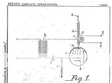
I think Schade would be embarrassed to learn some people are now trying to attach his name to an otherwise well-know and basic concept. The following predates Schade by four years, and its exactly the same thing. Schade didn't invent anything, he was just describing how well-know engineering principles could be applied to the then-new beam tetrode. Same thing applies to pentodes, as he well knew.
Last edited:
One should look at the non linear curvature for both the output tube and the non-linear driver load impedance, for the shunt feedback case. As the output tube gets more aggressive gm at higher current, the shunt feedback is pulling the driver down into lower current/higher Rp where it now has more neg feedback effect. Can this be made to compensate linearly just like a triode? Since one (output) is going to higher current and the other (driver) toward lower current, seems this can only simulate class A P-P cancellation.
I think it is kind of different: summing of transfer functions with 2'nd order distortions in counter-phase, versus multiplying them.
- Status
- This old topic is closed. If you want to reopen this topic, contact a moderator using the "Report Post" button.
- Home
- Amplifiers
- Tubes / Valves
- Most linear triode-strapped pentode