For Schade, the driver either needs a pentode with plenty of cathode degeneration to linearize it's V to I transfer, or a triode with lots of cathode degeneration to raise the output Z, or a series loading resistor to the output grid to linearize it's loading. These all throw gain away too. No clear winner.
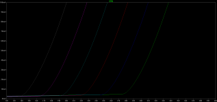
Nonsense. This design performs as designed. The local (Schade) NFB works as intended: going a long way to cleaning up the pentode nastiness that was all too evident when running open loop without any feedback connected.
The inclusion of local NFB does kill some gain, and degrade the estimated THD, by steepening the loadline. However, most of that THD is h2, and is nulled by the balanced topology, and the measured gain / phase corresponded exactly with the design nominal gain with 0% error.
Voltage feedback to: grid-to-cathode. Other than concern for phase, why should it matter to Schade transform which end gets feedback?
In the Vixen design, the idea was to "jump over" the reverse transfer capacitance of the 807s to avoid making a high pass filter that would compromise the open loop high frequency performance.
Attachments
Nonsense. This design performs as designed. The local (Schade) NFB works as intended: going a long way to cleaning up the pentode nastiness that was all too evident when running open loop without any feedback connected.
The post you replied to was talking about the driver - surely schade only cleans up the output tube - not the driver?
It's Miles' style, to say "I object" actually confirming.")
Then you and smokingamp must be using some sort of private language that says something to you two and something else to the rest of us. Smokingamp said that the driver needs to be a pentode, or triode without cathode bypassing to drive up its effective r(p).
I don't see where he's getting that idea. The local NFB increases loading, but it's still manageable, at least here it was.
There are some ham radio rigs that run these tubes at a lot higher voltage in SSB / CW mode (e.g. the Kenwood 520-530). It will shorten the life of the tube but not as much as one would think. Forced air cooling has a lot to do with it.
AM
Yep, my Kenwood TS830s does it . I was first surprised by the 100watt output (on SSB mode) obtained from a 6146B pair : the B+ is 980V
So i googled and found many posts explaining this op.point was absolutely normal . But you're right : the blower must be on, and avoid continuous sine wave (i'm not QRV on CW
, "no code" HAM ) The tubes i purchased the TX with were ... the original ones ...30 years old ! I reached New York city one week ago from Paris , with a single dipol ! Cheers
Nonsense. This design performs as designed. The local (Schade) NFB works as intended: going a long way to cleaning up the pentode nastiness that was all too evident when running open loop without any feedback connected.
No nonsense about S-A´s explanation, it says it all!
Remove GFB and feed the signal directly to the LTP of your amp and see what happens.
Last edited:
The inclusion of local NFB does kill some gain, and degrade the estimated THD, by steepening the loadline. However, most of that THD is h2, and is nulled by the balanced topology, and the measured gain / phase corresponded exactly with the design nominal gain with 0% error.
Are you talking about the loadline of the driver or the loadline of the output tube here?
...I would have thought that because a schadoid output stage effectively functions as an I-V converter, it in turn needs to be fed by a current source which by definition becomes more efficient as its output impedance increases.
I'm not quite following the output stage I-V converter analogy. The driver can be implemented in either current mode (driver is a V-I converter loaded by the feedback network) or voltage mode (feedback voltage is subtracted from drive voltage). I guess in current mode you could think of the feedback resistor as a current-to-voltage converter...
Either way, I have been thinking about the Schade output stage as a voltage follower. With 100% feedback in voltage mode it is a unity gain output stage. With current mode feedback it is a voltage follower for the grid-to-plate voltage across the feedback resistor. The relationship of gain, impedance, and gm follows the cathode follower equation e.g. Zout = 1/gm.
Cheers,
Michael
OK, I get it. What I'm calling the current mode driver, feeds both a I-V converter and a voltage follower.
The input V-I converter (current mode driver) develops a voltage drop across the feedback resistor, which is approximately the output voltage. You can see the combination of feedback resistor and "plate follower" as a power amplifying I-V converter.
It's transfer function is very similar to developing the full voltage swing across a resistor = to the feedback resistor and then buffering it with a cathode follower.
Cheers,
Michael
Attachments
Since we are talking about Schade local FB, what about using it with triode output tubes to lower the rp? Say, for example, the 801A. You don't gain any efficiency benefits but you ease the transformer requirements.
You can, but the more of voltage gain has an output stage, the better will be the result. That's why we prefer pentodes.
IIUC, this is due to the higher FB percentage afforded by the additional gain without placing undue burden on the driver?
Right.
On the other hand, how much feedback is needed to reduce the effective Rp of an 801A to 2K ohms or less? It's already linear!
Which is a way of saying that I think Schade feedback is an excellent idea for use with high impedance triodes.
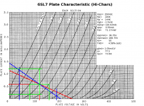
If you use a current mode driver, there is no additional voltage headroom needed. We're talking about mu from 8 to 30 or more. You will get effective Rp=1/gm which means that you can run your 801A at an effective Rp of about 600 ohms. The 35tg below has an effective Rp of about 400 ohms.
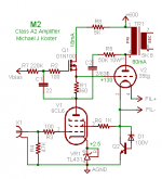
Once you go to all this trouble, you'll probably want to drive the grid properly into A2 operation.
But don't tell anyone you can turn a 100TH into a 100TL... Doh!
Which is a way of saying that I think Schade feedback is an excellent idea for use with high impedance triodes.
If you use a current mode driver, there is no additional voltage headroom needed. We're talking about mu from 8 to 30 or more. You will get effective Rp=1/gm which means that you can run your 801A at an effective Rp of about 600 ohms. The 35tg below has an effective Rp of about 400 ohms.
Once you go to all this trouble, you'll probably want to drive the grid properly into A2 operation.
But don't tell anyone you can turn a 100TH into a 100TL... Doh!
Attachments
JoshK>You don't gain any efficiency benefits but you ease the transformer requirements.
You can reduce plate impedance (dynamic resistance), but the static resistance
does not change. To get any power out you still need big voltage swing, and a
transformer with a high impedance primary winding. Linearity and damping factor
are improved, but "transformer requirements" aren't any easier or different at all.
I sometimes forget this myself, you can't skip drawing out the loadlines...
- Status
- This old topic is closed. If you want to reopen this topic, contact a moderator using the "Report Post" button.
- Home
- Amplifiers
- Tubes / Valves
- Most linear triode-strapped pentode