JoshK>You don't gain any efficiency benefits but you ease the transformer requirements.
You can reduce plate impedance (dynamic resistance), but the static resistance
does not change. To get any power out you still need big voltage swing, and a
transformer with a high impedance primary winding. Linearity and damping factor
are improved, but "transformer requirements" aren't any easier or different at all.
I sometimes forget this myself, you can't skip drawing out the loadlines...
I think Josh is referring to the difficulty of building a full range OPT for a high impedance triode, especially a DC biased SE transformer. The 801A has a plate resistance of about 4K ohms. To achieve a decent damping factor, I would spec an OPT primary impedance of 16K or 20K. Most builders try to get by with something like 11K-12K ohms that is commonly available.
One problems is getting enough inductance, even with all those turns needed. DCR starts to become an issue at some point with high turns count and smaller wire. Then at the high frequency end, all those turns need to be isolated from one another to reduce the winding capacitance.
So I would agree, that lowering the effective plate resistance using local feedback is a huge win for tubes like the 801A, 211, 100TH, etc.
NB if you use direct coupled feedback, the DC plate resistance does change and you will find yourself needing regulated B+...
Cheers,
Michael
Don't forget the circuit the tube is in
While I am waiting to move into our new house (supposed to be ready over a week ago) I have all my gear packed up. Only thing I am able to use is the computer so I installed LtSpice and have been playing around with it.
It has been suggested to me that the RH807 is inferior to the RCA Handbook #20 phonograph design or that the 12AT7 is inferior to the 12AX7.
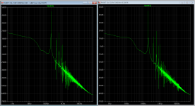
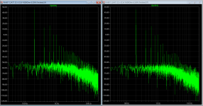
I am attaching some screenshots of the FFT that I managed to get in LtSpice with the output in same biasing (Vg2, Va, Rc, Vg1 etc).
The first is on the left comparing the RH807 driven by the 12AX7 and on the right the RH807 driven by the 12AT7 and the second picture is the difference between on the left the RCA with the 12AX7 and on the right the RH807 with a 12AX7. I do not yet fathom all the implications of these FFT but undoubtly the more knowledgeable amongst the readers will be commenting.
To me it appears that the design is of greater importance than the tube itself.
PS I am not saying that these designs presents the latest and greatest results, I am just comparing two different schematics with same tubes and output configuration and only changing the driver configuration.
PS2 the text in the headlines is not correct: all output configurations are the same.
Enjoy
AM
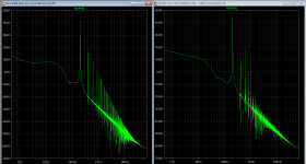
While I am waiting to move into our new house (supposed to be ready over a week ago) I have all my gear packed up. Only thing I am able to use is the computer so I installed LtSpice and have been playing around with it.
It has been suggested to me that the RH807 is inferior to the RCA Handbook #20 phonograph design or that the 12AT7 is inferior to the 12AX7.
I am attaching some screenshots of the FFT that I managed to get in LtSpice with the output in same biasing (Vg2, Va, Rc, Vg1 etc).
The first is on the left comparing the RH807 driven by the 12AX7 and on the right the RH807 driven by the 12AT7 and the second picture is the difference between on the left the RCA with the 12AX7 and on the right the RH807 with a 12AX7. I do not yet fathom all the implications of these FFT but undoubtly the more knowledgeable amongst the readers will be commenting.
To me it appears that the design is of greater importance than the tube itself.
PS I am not saying that these designs presents the latest and greatest results, I am just comparing two different schematics with same tubes and output configuration and only changing the driver configuration.
PS2 the text in the headlines is not correct: all output configurations are the same.
Enjoy
AM
Attachments
Last edited:
Use a later start time, give DC time to settle, your FFT should not slant that much.
Also add ".options plotwinsize=0" without the quotations marks...
Thanks, I'll try that in the morning.
AM
On the other hand, how much feedback is needed to reduce the effective Rp of an 801A to 2K ohms or less? It's already linear!
Which is a way of saying that I think Schade feedback is an excellent idea for use with high impedance triodes.
If you use a current mode driver, there is no additional voltage headroom needed. We're talking about mu from 8 to 30 or more. You will get effective Rp=1/gm which means that you can run your 801A at an effective Rp of about 600 ohms. The 35tg below has an effective Rp of about 400 ohms.
Once you go to all this trouble, you'll probably want to drive the grid properly into A2 operation.
But don't tell anyone you can turn a 100TH into a 100TL... Doh!
Bingo! That was precisely my line of thinking. I still a relative newb, especially compared with many of you, so I ask a lot of questions to see if I get the concepts.
I think Josh is referring to the difficulty of building a full range OPT for a high impedance triode, especially a DC biased SE transformer.
Exactly. Although Kenpeter suggests that the OPT wouldn't change. Why not?
NB if you use direct coupled feedback, the DC plate resistance does change and you will find yourself needing regulated B+...
I didn't follow that.
OK, I am full of questions today.
Michael. In your 35tg schematic, you show a mu follower with a pentode as the bottom element. I thought you couldn't stack a CCS on top of another CCS-like device (pentode) without "folding" or providing a parrallel DC path to common. Am I missing your parrallel DC path?
Michael. In your 35tg schematic, you show a mu follower with a pentode as the bottom element. I thought you couldn't stack a CCS on top of another CCS-like device (pentode) without "folding" or providing a parrallel DC path to common. Am I missing your parrallel DC path?
OK, I am full of questions today.
Michael. In your 35tg schematic, you show a mu follower with a pentode as the bottom element. I thought you couldn't stack a CCS on top of another CCS-like device (pentode) without "folding" or providing a parrallel DC path to common. Am I missing your parrallel DC path?
The mu-follower is a gyrator, which provides a DC reference based on the adjustable bias voltage. This keeps the driver DC plate voltage stable. The AC load on the pentode is the feedback resistor, cap couled in this circuit, to the 35tg plate.
Something to think about, the RC time constant of the feedback needs to be equal or longer than the RC time constant of the gyrator for frequency stability.
My point about direct coupled feedback from plate to grid is that the effective plate resistance is 1/gm down to DC, meaning on the order of 5mA plate current change per volt of B+ change.
That to me calls for regulation of the B+, or something like the SE Schadeode circuit where I have a bypassed 1K resistor in the cathode that adds 1K to the DC plate resistance.
As for the transformers, there are probably a number of factors to take into account, but I have noticed first that the lower impedance transformers seem to perform a little better, given the same Rp to Zpri ratio, and second that any given transformer performs a lot better when driven by a low effective plate impedance like that obtained with local feedback.
Whether those factors "ease" requirements is still a question I suppose.
Michael
Use a later start time, give DC time to settle, your FFT should not slant that much.
Also add ".options plotwinsize=0" without the quotations marks...
Here the updated screendumps. Text in headings is correct, output stages are identical configured with identical voltages only driver is changed and driver configuration is changed.
Look forward to more comments, thanks.
AM
Attachments
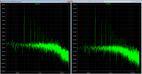
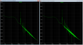
The 12AX7 appears to have a slightly lower noisefloor than the 12AT7. However what is more important is that while I experimented with different values for the "load" on the 6L6GC there are marked differences between the RCA (plate to driver's cathode) and the RH807 (plate to driver's plate).
The RH807 shows hardly any distortion (in plate voltage) when changing the plate load (driven at max power) while the RCA model is rather sensitive. This confirms that the plate to driver's cathode feedback is not as good a selection.
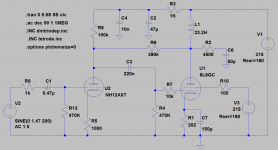
I hope this helps someone, for me the choice is clear: I'll be opting for the lower noisefloor of the 12AX7 (versus 12AT7) and the lower noisefloor of the RH807 (versus the RCA model). Am attaching the schematic.
Thanks to all for their suggestions and help.


AM
The RH807 shows hardly any distortion (in plate voltage) when changing the plate load (driven at max power) while the RCA model is rather sensitive. This confirms that the plate to driver's cathode feedback is not as good a selection.
I hope this helps someone, for me the choice is clear: I'll be opting for the lower noisefloor of the 12AX7 (versus 12AT7) and the lower noisefloor of the RH807 (versus the RCA model). Am attaching the schematic.
Thanks
to all for their suggestions and help. AM
Attachments
I see the mistake I made 2 years ago: I read on the forum that parallel feedback by voltage in output stage was called "Schade feedback", but when later fond the original Schade paper discovered that in his example he used feedback in series with input signal. I apologize for the confusion. ")
So what everyone calls 'Schade' feedback is not Schade feedback at all?
Actually Schade did not insist on using feedback in series, but his example showed it. What he insisted on, that 6L6 tube is actually good for audio when used with local feedback. His tables demonstrated results with local feedback across output stage. It could be either in parallel or in series, results will be the same except how driving power is distributed: either higher current demand, or higher voltage demand. The problem was, when RCA started production of 6L6 audio designers did not like it because wanted more linear tubes and continued using triodes. RCA wanted higher demand, so I assume it was the main reason for the article publication.
But you are right, I was wrong when insisted that Schade feedback is the one applied in parallel with input signal, even though it is common here on the forum to call such local feedback in output stage "Schade Feedback".
Like this?
A= high current
B= high voltage
A= high current
B= high voltage
An externally hosted image should be here but it was not working when we last tested it.
No.
In the original Schade article interstage transformer was used, and feedback was applied to the side of the secondary opposite to the one that was connected to the grid. It was applied in series with input signal.
On your picture in both cases feedbacks are applied in parallel with input signal.
In the original Schade article interstage transformer was used, and feedback was applied to the side of the secondary opposite to the one that was connected to the grid. It was applied in series with input signal.
On your picture in both cases feedbacks are applied in parallel with input signal.
Don´t read the original paper as the bible. There are more ways of doing what some call Schade and others call anodefollower with feedback. They all end up the same: The curves changing from tetrode to triode-like.
I think nobody reads it as a bible. The question was, either to attribute any local feedback in output stage from anode to control grid to Schade, or not.
Are there any earlier examples of feedback to a pentode or tetrode grid circuit?
O. H. Schade also used a curve tracer to show that plate-grid feedback results in a triode-like curve.
In his paper, he uses a simplified circuit to illustrate the principle.
Does it really matter as long as the plate signal subtracts arithmetically from the grid signal?
O. H. Schade also used a curve tracer to show that plate-grid feedback results in a triode-like curve.
In his paper, he uses a simplified circuit to illustrate the principle.
Does it really matter as long as the plate signal subtracts arithmetically from the grid signal?
- Status
- This old topic is closed. If you want to reopen this topic, contact a moderator using the "Report Post" button.
- Home
- Amplifiers
- Tubes / Valves
- Most linear triode-strapped pentode