There is insufficient voltage between drain and source of the second MOSFET (IRF710), and it will clip very easily with very little headroom.This is a stupidly simple mod...
Reducing the 39k drain resistor to 22k should improve this situation a lot. To retain balance between the two phases, split the 47k source resistor into 22k+22k, and take the output from the junction of the two 22k resistors.
If I understand correctly, the OP is after a gain cell / compressor, while your circuit is designed to amplify a signal and then split it into two phases.
-Gnobuddy
Yes I think Skyra is responding to the OP...OP...Lol, I kind of derailed the phase inverter subject.
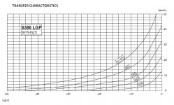
The only currently made tube that can truly pull down 20db of audio and still eek some signal out is the JJ6386 which costs $120 each. With 2 strong 6BA6's you can mimic the 6386 dual triode and there are plenty of them around. But you have to burn them in and match a pair on a curve tracer. Which I have done. But I would like a cheaper easier solid state plug in replacement for the 6386. They make solid state 12AX7's for guitar amps. Thats easy, but like PRR said mimicking the curve of a tube down to -60v grid bias is quite a challenge.
Would adding a CCS to a regular tube (12AT7) stretch out the range of negative grid bias to current output? or will the tube still just turn off abruptly at a certain point?
Attachments
If the goal is to use an FET to make a compressor with a 20 dB compression range, that should be entirely possible - by using a circuit designed around an FET, not a valve.The only currently made tube that can truly pull down 20db of audio and still eek some signal out is the JJ6386 which costs $120 each.
I know very little about valve compressors, but they seem to be based on varying the transconductance to vary the voltage gain. As PRR pointed out, FETs have transconductance that goes fairly abruptly from nearly zero to very high, and this suggests that variable transconductance may not be the best way to implement audio compression using an FET.
There is a different way, however. The channel resistance (between source and drain) of an FET can vary over a very wide range, from megohms down to kilo ohms or even less, depending on the FET. This channel resistance is also reasonably ohmic (linear) for small voltages - if you keep the incoming voltage down to no more than a few tens of millivolts, the FET doesn't care if the source is more negative than the drain, or the other way around. You can treat the FET as a variable resistance, in other words.
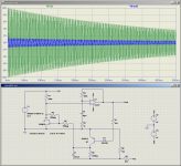
Here is a crude compressor circuit I threw together in LTSpice. It's more of a leveller as shown, as the compression ratio is pretty extreme, but I got the feeling that was what you were looking for. I have no idea how this might sound, but it might provide a starting point for experimentation.
The working principle is very simple. R1 and J1 (which must be a depletion mode device) form an adjustable voltage divider, whose attenuation is set by the channel resistance of the FET. The signal from the voltage divider is fed to the op-amp, which amplifies it. The output of the op-amp drives Q1 / R6 / C1, which is a simple rectifier circuit that generates the control voltage which is fed back to the gate of J1, in such a way as to try to keep the output signal from the op-amp at a constant level.
R4/R5 are there to reduce harmonic distortion caused by slight non-linearity in the JFET (the famous square-law characteristic.)
R3 sets the compression ratio (gain of the op-amp), and in this very simple circuit, the threshold is set by the roughly 1.2 volts needed to make Q1 and D1 start to conduct.
R8/R9 set the quiescent gate voltage of the FET. The idea is to have the FET biased off (high channel resistance), but not so far off that there is an unacceptable delay in attack time while the control voltage builds up to the point where it can start throttling down the signal.
-Gnobuddy
Attachments
Wow thank you Gnobuddy, What a nice and simple circuit. There is a famous audio compressor based on this principal called the UREI 1176. Any music you listen to made after 1970 has at least one element of the mix that was run through an 1176. Every studio has at least a couple of them.
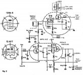
That said, My whole goal is to be able to replace the 6386 tube directly with a solid state device so I can replace the expensive tube in my current compressor for good! I've done some digging around and found some schematics showing a replacement for a 12BA6 remote cuttoff tube that uses a dual gate mosfet. But I'm not sure if it will really go down to the low grid voltages I need. It was a starting point for what I have now.
That said, My whole goal is to be able to replace the 6386 tube directly with a solid state device so I can replace the expensive tube in my current compressor for good! I've done some digging around and found some schematics showing a replacement for a 12BA6 remote cuttoff tube that uses a dual gate mosfet. But I'm not sure if it will really go down to the low grid voltages I need. It was a starting point for what I have now.
Attachments
...As PRR pointed out, FETs have transconductance that goes fairly abruptly from nearly zero to very high...
I was saying that Gm stays high even as Id gets _low_, too low to pull the load of the next stage.
In tubes driving transformers, I don't like to see <2mA at the low gain-current end of the CV. This is arbitrary, but less than 2mA is likely to be unable to drive a transformer's parasitics.
In a 12AU7-based limiter, I did cheat down to <1mA, but THD was rising fast at that point.
THAT chips. No fake. ALL the troubles we've had with tubes for 80+ years go-away with a THAT VCA and sidechain. Stick a 6BQ7 on top and tell people "tube limiter".
After many unsuccessful attempts to build a DIY compressor I really liked, I gave up and bought a $100 (now apparently raised to $130) ART Tube MP/C. ( ART Tube MP/C Tube Preamp / Opto Compressor-Limiter / DI | Sweetwater )ALL the troubles we've had with tubes for 80+ years go-away with a THAT VCA and sidechain. Stick a 6BQ7 on top and tell people "tube limiter".
I liked it so much I ended buying another, and then a third. I've used them with bass guitar and with vocal microphones. These little boxes make nice preamps, lovely DI boxes, and well-behaved compressors when that's called for. A very useful tool to have at your disposal.
An entire MP/C costs barely more than price of a single 6386 variable-mu tube.

-Gnobuddy
Exactly what the Summit TLA100 is! VCA with a tube in the signal path. even has 990 op amps as output devices. The tube is set up as a cathode follower so its not even amplifying, Lol.ALL the troubles we've had with tubes for 80+ years go-away with a THAT VCA and sidechain. Stick a 6BQ7 on top and tell people "tube limiter".
Well I guess I'll just have to figure out how to run a VCA on tube voltages and scale the control voltage properly. Then fit it all into a package the size of a tube. Ha!
There is insufficient voltage between drain and source of the second MOSFET (IRF710), and it will clip very easily with very little headroom.
Reducing the 39k drain resistor to 22k should improve this situation a lot. To retain balance between the two phases, split the 47k source resistor into 22k+22k, and take the output from the junction of the two 22k resistors.
If I understand correctly, the OP is after a gain cell / compressor, while your circuit is designed to amplify a signal and then split it into two phases.
-Gnobuddy
Well, then this guy is similarly ignorant because he is using the exact same idea....
BTW the amp (NIVS) works perfectly with the described mod, pumping out 17 Watts of undistorted sine wave from 30Hz to 20k. How is it possible ?
Attachments
Well, then this guy is similarly ignorant because he is using the exact same idea....
BTW the amp (NIVS) works perfectly with the described mod, pumping out 17 Watts of undistorted sine wave from 30Hz to 20k. How is it possible ?
I should clarify that I haven't tested that circuit I posted so I am ignorant of how it measures in practice
It is biased so that 1/3 to 1/4 of the B+ is on the source loading resistor (and same on the drain loading resistor). That leaves 1/3 to 1/2 the B+ across the MOSFET. This gives the maximum symmetrical output from both phases.
Just received a small PCB to test a FET-odyne style PI coincidentally.
Last edited:
The FET-odyne is my go-to for PP amps. I've used it in 5 different amps, including two documented here:
So, I built a Broskie Bastode…
Just what the world needs - another EL84 amp
So, I built a Broskie Bastode…
Just what the world needs - another EL84 amp
No, he's not; the problem with the circuit you showed earlier isn't the topology, it's the values.Well, then this guy is similarly ignorant because he is using the exact same idea....
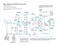
In your post #80, your circuit diagram (schematic) shows 131 volts at the FET source, and 137 volts at the drain. That means there are only 6 volts across the MOSFET; if the source rises 3 volts, the drain falls 3 volts, leaving 0 volts across the MOSFET. Even if you had a mathematically perfect MOSFET, the circuit you showed would clip as soon as the output approaches 3 volts peak (6 volts peak-to-peak.)
The problem is the 134 volts at the gate. It's far too high to allow direct-coupling the MOSFET. For a MOSFET source-o-dyne, the gate should be at about one-quarter of B+, in this case, (270/4) or about 67.5 volts. This will allow nearly 135 volts peak-to-peak from each of the two outputs, instead of the tragically small 6 volts you have now.
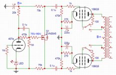
When you say "the amp", I assume you mean the tube amp you showed in post # 88.BTW the amp (NIVS) works perfectly with the described mod, pumping out 17 Watts of undistorted sine wave from 30Hz to 20k. How is it possible ?
How is it possible? Because this one is designed correctly. The schematic shows the MOSFET gate at 75-90 volts. With a B+ voltage of 300 - 360 volts, this will put the MOSFET source at one-quarter of the B+ voltage, exactly where it should be for maximum headroom before clipping. The MOSFET will be able to put out about 150 volts peak-to-peak at each of its two outputs before clipping.
Again, compare this with the roughly 6 Vpp maximum output from the circuit in post #81 (which can easily be reduced to nothing at all if a different 6N2P with slightly different parameters is plugged in.)
-Gnobuddy
you could try a "cathodyne" with the LND150 used in ECC83 fashion running at under 1 mA current but it doesn't sound appealing to me. I would opt for something else like a Mullard style circuit with a small jFet SE input and a double triode in LTP mode.
Hello! Space in the amp is very limited and I only have space for a single triode input tube and a FET phase inverter. So that's going to be the topology, I'm afraid. I need a proven schematic from a working amp - don't want to blow anything up. It's a cherished amp.
.
Last edited:
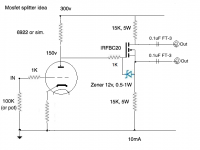
Seem to me ~17ma.Very useful - I don't need as much current through the Mosfet - your design looks like 28mA.
Try 100-125v, need some headroom for mosfet swing.I was thinking more like 10mA. B+ will be about 300v. So I guess the voltage on the anode of the first resistor loaded triode should be 150v, right? Like half of 300v?
Andy,
You might be interested in reversing the order and making a williamson style amp.
I experimented with an LND150 split load phase inverter for the input driving a small signal dual triode.
Excellent balance and the distortion from the LND150 was at the residual of my HP8903 analyzer.
Steve
You might be interested in reversing the order and making a williamson style amp.
I experimented with an LND150 split load phase inverter for the input driving a small signal dual triode.
Excellent balance and the distortion from the LND150 was at the residual of my HP8903 analyzer.
Steve
These suggestions are welcome for a different amp, but for the one in question I need to use a particular single triode followed by a phase inverter. I only have room for one tube before the output stage. I could use a long tailed pair (which is in there right now) or a double triode as a voltage amp plus concertina, but there's a particular single triode I want to use in this amp. Outputs are PPP 6S4A.
- Home
- Amplifiers
- Tubes / Valves
- MosFET or other semiconductor substitute for cathodyne?