The largest DC link stuff I typically see is 8 to 30 uF at 4kV lol, and these are the size of a drinks can.
I have some 15uF PP films which are half the size, and if I recall 1500V rated, some of the old RS (maybe Maplin) PP range.
I have a Monacor branded 250V rated 47uF PP film that might be worth a try, if they're still available.
I can't find them, but I found this:
Not cheap...
C4AQLBW6130A3NK Capacitor Polypropylene DC-Link 130uF Leads for KEMET: Amazon.co.uk: Business, Industry & Science
Last edited:
The ones I used are sold by RS. They're all box shape so need a bit of thought about mounting them. I use M3 hexagonal nylon standoffs with solder tags on top.
https://uk.rs-online.com/web/p/polypropylene-film-capacitors/6842295/
Ale does some PCBs on Bartola Valves for the WIMA ones
WIMA DC Link – Bartola(R) Valves
I'm very pleased at the improvement in sound I'm getting.
https://uk.rs-online.com/web/p/polypropylene-film-capacitors/6842295/
Ale does some PCBs on Bartola Valves for the WIMA ones
WIMA DC Link – Bartola(R) Valves
I'm very pleased at the improvement in sound I'm getting.
Off topic, but since we're on the subject of bypass caps here's a brief shootout I just did on the cathodes of my 300b outputs. In order of preference:
- Vishay DC Link Cap, 40uF, 900v
- ICW SA Clarity Cap, polypropylene, 47uF, 630v
- RS electrolytic 100uF, 450v
- ICW PW polypropylene cap, 40uF, 160v
- Aerovox motor run cap, polypropylene, 40uF, 450v
My current choice of cathode bypass (only one in the amplifier, the first cathode)
Yunxing SPT1CM102G12OR
https://datasheet.lcsc.com/szlcsc/2007091907_Yunxing-SPT1CM102G12OR_C698129.pdf
I am waiting for a 1500uF version from a different brand to test it against but I don't think it will be necessary at all.
FYI: I also tried Nichicon UKA1C102MPD but there was no noticeable difference.
Last edited:
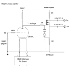
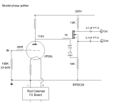
Hi guys. I now have to build a push-pull amp for a friend who's waiting for it, so I have to have a working design for a phase splitter ASAP. Being only used to tubes I don't fully understand how to design this mosfet splitter and need your help so I can get building. I have some IRFBC20 which Eli Duttman recommends. I now have to complete the following design. I need to know the voltage going into the gate for a start. Then the values for the 2 resistors top and bottom of the mosfet. I've put in 5K but suggest something better. And anything else needed in the design? What diodes should I use? Output stage is EL12n in push-pull, easy to drive.
Thanks for your help in finishing off this design!

Thanks for your help in finishing off this design!

Yes. Voltage at source will be about 111V, so current through mosfet and resistors ~11 mA, mosfet dissipation ~1.1 watts. Reverse transfer capacitance is at a minimum at Vds>20V, which will be the case for all operating conditions. You probably don't need that much current to drive EL12N grids (pentode connected?), so resistors could be say 22k for 5mA, but up to you.
Yes, it is possible at power up for the gate to be pulled high while the source is pinned low as it charges the coupling cap through the grid current of the output valve, busting the gate open. (You really only need one Zener, though back to back Zeners don't hurt of course)"Here is a question more than a comment: Are the Zener diodes needed if the load is not inductive? I know they won't hurt, but are they necessary?"
EL12n are triode connected. Thanks - I might go with 15K resistors, have some nice wirewounds.Yes. Voltage at source will be about 111V, so current through mosfet and resistors ~11 mA, mosfet dissipation ~1.1 watts. Reverse transfer capacitance is at a minimum at Vds>20V, which will be the case for all operating conditions. You probably don't need that much current to drive EL12N grids (pentode connected?), so resistors could be say 22k for 5mA, but up to you.
If I'm using IRFBC20 do I need heat sinks for them? It would be around 110V at 7.3 mA.
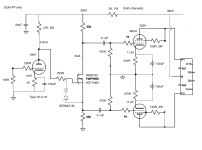
With that much voltage on the cathode resistor, it doesn’t really make a difference if the FET is E-mode or D-mode. Just has to handle the voltage and have its capacitances remain linear. Just keeping VDS up near 50V or more will do this with just about any HV FET. Some do better at lower VDS so depening on type it could go lower transparently.
It's directly coupled, so no additional bias network neededEnhancement mode MOSFET, if I'm not mistaken need a bias network on the gate (voltage divider).
- Home
- Amplifiers
- Tubes / Valves
- MosFET or other semiconductor substitute for cathodyne?

