Datasheet value is 70 pF, which, I agree, is a lot compared to most small-signal BJTs. But it's still less than a typical 12AX7 gain stage...The ZVN0545A mosfet look good but much higher capacitances
For this application, (a source-o-dyne or source follower), input capacitance will be much less than the datasheet value of Ciss, because only a small fraction of the signal voltage actually appears across gate and source, and the capacitance is therefore bootstrapped.
If the source signal is 90% as big as the gate signal, the effective input capacitance is reduced from 70 pF to 7 pF. If the source signal is 95% of the gate signal, input capacitance is reduced to just 3.5 pF. At that point the stray capacitance from a typical valve socket becomes more relevant than the input capacitance of the source follower or source-o-dyne!
We only have to worry about the full 70 pF input capacitance if the source is connected directly to ground as far as AC goes (i.e. we have a fully bypassed source resistor).
-Gnobuddy
In voltage follower service, the critical FET parameter is reverse transfer capacitance (Crss). Keep in mind the fact that a "concertina" phase splitter is a "tricked out" voltage follower. While taking signal from both source and drain must have some impact, Crss for both the ZVN0545A & ZVP0545A is small at 4-5 pF.
see, aint yall glad i revived this thread? anyway...BOOM! i made some smoke! but not where i expected. on my fingertips. the PI worked perfectly, though i did change a few things to suit what i found... 3.3 and 1.1M down to 150 and 470K. still settled at about 30V off 120. poifect. for now, who cares about soaking too much power? the 1/4 watts didnt blow up at least.
PP output using the ignomious 1p24b russian things. lil buck convertor for HT. PC supply for the 12V to drive the bucker and supply -12v bias. 10K:something ridiculous OPT A&R 2632. works out to be 3.3K:16. i had a 16 ohm squawker on hand.
that worked, so i got all enthusiastic... i should have stopped there...
on with the preamp!
1j29b.
and for some damn reason the G2 1K resistor started smoking... it did some strange things, filaments really started glowing, iunno. gave it -2V bias and everything! swapped it over for another! double checked all the wire outs...nope. either something weird is going on or i have a different version of it.
i know theres another variant but that aint what i got... maybe i have to smash one open to see whats what better.
then the filament wire got loose and tapped the HT and mr bucky decided to fry... one well smoked UF diode... tasty. goes with my fingers from yanking out that screen resistor.
anyway. the PI works. if only i had known it was this simple (cheers gnobuddy for clarifying the last little piece of the puzzle). though i am noticing a bit of positive going spiking on the source-HT side output... excess gate capacitance perhaps? time to order some of the LND150's everyone is going on about.
yippee. im halfway there!
here comes th challenging part... making a multi output flyback... two isolated 2.4V for filaments. 250V HT. 40V for power amp bias(room to adjust). either divider or yet another winding for 125HT on the preamp. another 4-5V for preamp bias...
rather be running off one plain 12V gel cell than run several batteries of strange voltages.
these directly heated cathodes are little pricks to use. maybe i will give up and use a 12ax7 preamp instead...
oh yeah, the whole idea was to make a tiny, all tube busking amp... though considering everything, i may as well just use normal tubes and go "not so compact".
Last edited:
Thanks for the link. Normally with a tube concertina I've seen equal resistor values top and bottom. I guess because typically a resistor was used in the plate of the preceding tube, so the concertina's grid was about half the voltage of the B+.
If this SS concertina were used with a preceding stage using a plate choke the situation would be different. Just wondering how to proceed with a setup where the gate of the device would be virtually at the same voltage as the HT?
You will need to cap couple it to the gate, then reference the gate to 1/4 of the HT. This could be done cheap and dirty (bootstrapped) or more elegantly (proper stable reference with MJ's thingy come to mind).
However, the HT is too small to do anything decent with (me think lots of clipping will be happening with only 100v).
To solve this, you need a negative rail, and the gate will also need to be negatively biased. After that, you will need cap couple phased outputs to some kind of driver stage. If the input has HUGE gain, you might get away with source follower (ideally with active load).
Usually the input stage does not have quite enough gain though, so you can consider a proper differential driver stage with a valve/tube. If you are driving something easy (maybe 6V6 or el84) then it can work well enough. If you are driving something demanding (worst example, 300b) then it can be a challenge.
you can also use an actively loaded source follower after the driver... It won't take much space.
My 2cents.
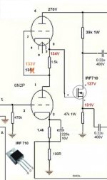
Same DC voltage, but much lower input resistance (114k instead of 825k.) I was aiming for an input resistance close to the usual 1 megohm grid bias resistor used in most cathodynes.3.3 and 1.1M down to 150 and 470K. still settled at about 30V off 120.
The lower input resistance may not matter if the output resistance of the previous stage is low enough (perhaps you're using a low ra triode?) I was thinking of a conventional 12AX7 stage, which with a 100k anode load typically has an output resistance around 40 kilo ohms. That's high enough to cause noticeable signal attenuation with a 114k input resistance of the next stage.
I'm not sure the LND150s are actually any better for this application. It's true that they are cheap, have low input capacitance for a MOSFET, and will handle 500 volts, all of which is nice. But they also have limited power handling ability (not so nice), and Idss is not guaranteed to be more than one milliamp (not so nice either). So LND150s may not always be the best choice.time to order some of the LND150's everyone is going on about.
I've just been discovering that from reading a current diyAudio thread titled "Russian rod tubes in a battery all-tube mini amplifier prototype".these directly heated cathodes are little pricks to use.
")
Do you think you'll get enough run-time? Valves are not known for good electrical efficiency.oh yeah, the whole idea was to make a tiny, all tube busking amp... though considering everything, i may as well just use normal tubes and go "not so compact".
It's summer in the northern hemisphere, and here in British Columbia, the wildflowers are in bloom and the parks are gorgeous. I've been putting together a little battery-operated portable amp as well, to have some outdoor fun with. But I went with a class-D power amp board and a Joyo American Sound (possible Sansamp Blonde rip-off) pedal to give it some (fake) "valveyness".
-Gnobuddy
Stocktrader, some indirectly heated valves/tubes are indeed not trivial to drive. Important is to recognize the requirements and design with them in mind.
Indirectly or directly heated does not define "better".
Limit the duty to only splitting phase and LND150 should be fine. Don't expect it to drive anything of consequence. If the miller capacitance of the following stage is high, then use something with lower output impedance in between.
I like IRFBC20 source follower (actively loaded with DN2540). Drives really long cables well too, but I would not make the claim that it could drive a golf ball through a garden hose.
Ian
Indirectly or directly heated does not define "better".
I'm not sure the LND150s are actually any better for this application. It's true that they are cheap, have low input capacitance for a MOSFET, and will handle 500 volts, all of which is nice. But they also have limited power handling ability (not so nice), and Idss is not guaranteed to be more than one milliamp (not so nice either). So LND150s may not always be the best choice.
Limit the duty to only splitting phase and LND150 should be fine. Don't expect it to drive anything of consequence. If the miller capacitance of the following stage is high, then use something with lower output impedance in between.
I like IRFBC20 source follower (actively loaded with DN2540). Drives really long cables well too, but I would not make the claim that it could drive a golf ball through a garden hose.
Ian
If you run from a 300 volt B+ and bias optimally to 1/4 of that at the gate, and keep source current to no bigger than a milliamp, you end up having to use source and drain resistors that are no smaller than 75 kilo ohms. I used 82 kilo ohms, which is appreciably larger than the 56k used in some Fender guitar amps.Limit the duty to only splitting phase and LND150 should be fine.
And this is the issue I ran into. Not Miller capacitance - with most pentode output valves, and with the amplifier restricted to electric guitar bandwidth, output stage Miller capacitance is too small to matter.Don't expect it to drive anything of consequence. If the miller capacitance of the following stage is high, then use something with lower output impedance in between.
The problem is blocking distortion and bias shift of the output valves when overdriving a guitar amp, caused by grid current flow through the coupling caps from the source-o-dyne to the output valve grids. Short of installing driver MOSFETS for the output valves, the only real fix is to provide a relatively quick discharge path for those coupling capacitors, by using not-too-big grid bias resistors for the output valves.
But the cathodyne / source-o-dyne then has to be capable of driving those not-so-big grid resistors. And the LND150 was marginal in my case.
Tubelab (George) mentioned that one in on of his many posts, and also mentioned that he had plugged one directly into a 12AX7 valve socket, and it biased up and worked.... DN2540...
For someone looking for a generic MOSFET to use as a source-o-dyne in a typical guitar amp, I think the DN2450 might be a better choice than an LND150 in many cases. Just remember not to touch the metal tab on the package when the amp is powered on, and to ensure that nobody else can, either!
-Gnobuddy
I dislike SMD parts. While rated for "only" 400 V., the TO-92 case DN2540N3-G, with a push on heatsink, might be preferred over the DN2450. Seems much safer to me.
That's certainly a good option. On the minus side you need that additional heatsink, on the plus side you're not limited to 1 mA drain current.While rated for "only" 400 V., the TO-92 case DN2540N3-G, with a push on heatsink, might be preferred over the DN2450. Seems much safer to me.
We don't actually need a depletion-mode MOSFET for source-o-dyne duty, since we're not self-biasing it anyway. Dropping the requirement for depletion-mode opens up the much larger world of enhancement-mode MOSFETs, and there is probably something suitable in a TO-220 package with a fully plastic-encapsulated tab, with no dangerous exposed metal at drain voltage.
I think the fully encapsulated version of the TO-220 package is referred to as a TO-220F, or maybe TO-220FP. Thermal resistance is higher than the exposed-metal version of the TO-220, but lower than a TO-92.
A quick search at Mouser turned this up: https://www.mouser.ca/datasheet/2/196/Infineon-IPA50R280CE-DS-v02_04-EN-1226155.pdf
Input capacitance is massive at 773 pF, but will be reduced to 5% - 10% of that in source-o-dyne mode, which should be fine, comparable to or lower than a typical half-12AX7 triode. Safe operating area restrictions still allow more than 20 mA of DC current flow at the full 500 volts Vds, and that's more than enough current for any source-o-dyne I can imagine. Thermal resistance without a heatsink is 80 degrees C / watt, so it would be best to keep power dissipation to no more than half a watt (which takes the junction to 70 deg C in a 30 deg C ambient temperature) unless a heatsink is used.
-Gnobuddy
Do you think you'll get enough run-time? Valves are not known for good electrical efficiency.
Could use something like a DM160 and get plenty of run-time in a battery powered amplifier if you use a class-d output. Little guy only takes 30mA at 1V and would definitely color the sound!
im baaaaack!
meh. i never did anything else with my little russian tubes after smoking the power supply... dammit. instead i pulled my old guitar amp apart again.
so i can say, that even an !RF840 appears to work as a "source-o-dyne"...
no idea how its capacitance affects things, or even really how its doing what its doing, but there you go.
an irf840 driving an el84 output stage. works.
even accepted a brief run with the coupling cap accidentally removed and having one leg grounded via the volume pot... um. didnt actually notice anything unusual at first, but after a minute the volume faded...then faded again upon adjustment...etc.
already a bit of an experiment, running an ecf80 on the input stage. (triode, pentode with triode morph, feeding 12ax7 stages feeding PI... still debating on if i should flip that order around a bit. pentode stage sounds nice, and very sensitive, but maybe better driven with a 12ax7 instead of its twinned triode.)
now, what to do with that extra valve stage i just opened up?
Last edited:
Could use something like a DM160 and get plenty of run-time in a battery powered amplifier if you use a class-d output. Little guy only takes 30mA at 1V and would definitely color the sound!
i´d prefer it over korg nutube !!
The pricing of the Nutube ($50 USD) makes it an unattractive choice for DIY, particularly when there are a vast number of unpopular NOS tubes that one can buy for a fifth of that price, or even a fiftieth of that price.i´d prefer it over korg nutube !!
Along with the limited availability and high price, the Nutube also comes with a very low mu (15, six times less than a 12AX7). It will be hard to get a voltage gain of more than six or seven times out of one. This is down in JFET territory.
In addition, the Nutube has a very low transconductance (54 uA/V, thirty times less than a 12AX7), and a very high ra (330k, four to five times higher than a 12AX7). Because of the high ra, it can't even drive a 500k pot without suffering substantial gain loss.
I can see the appeal for mass-manufactured Korg products (like the VOX MV50 amps). Korg isn't paying fifty bucks a pop, and they can stuff a Nutube into a PCB for far less money than dealing with a traditional tube. But for DIY, the Nutube just doesn't make sense to me.
-Gnobuddy

Hello, was hoping someone in this thread could help out with a little circuit I'm working on using the LND150.
I'm trying to emulate a remote cutoff tube with the mosfet. I'm using a big voltage divider to try and scale the mosfet grid voltage to plate current curve of the tube. the tube turns off at a very low -60 to -80 volts. Of course i'm only working with 0 to -3 with the mosfet.
Such a large divider shunts high end ac in conjunction with the gate C.
Lower voltage divider resistors start to affect the time constant of the control voltage. So I thought maybe stacking another mosfet with a dc blocking cap on top would enable me to bring back the shunted audio and keep the high dc resistance in tact for the control voltage.
Any thoughts on this would be much appreciated!
Attachments
I don't quite understand what you're trying to accomplish (make a MOSFET mimic a remote-cutoff pentode?), but I'll point out that none of your circuits includes a source resistor. Without one, you have very little chance of biasing your MOSFET correctly, which means the circuit won't work.Any thoughts on this would be much appreciated!
-Gnobuddy
A MOSFET is not "remote cutoff".
Also MOSFET voltages, both CV and signal, will be 10-20 times smaller than a tube.
The LND150 has action both above and below zero, which complicates the CV action.
The super-high and saturating transconductance of MOSFETs generally offer a *very* limited control range. At one end gain doesn't change much. At the other end the MOSFET current gets too low for useful signal. Specifically for LND150 my sim suggests only 3:1 maybe 4:1 range of gain above cutoff, 10dB-12dB. Far less than a tube.
MOSFETs are "good" amplifiers. A limiter needs a "bad" amplifier with a long non-linear zone.
Attachments
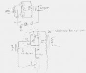
Thanks for the replies. Hello PRR, This is for an audio compressor. I have been able to get this to work. as in the circuit below. I can actually get a good 10 db of gain reduction out of it before it totally farts out. Especially with a couple of the circuits in parallel. I would love to be able to get it close to a 6ES8 or similar. It IS close in fact but the voltage divider (2M to 200K) to knock down the control voltage into the 0 to -3V range has a audible effect over the sidechain RC time response. Especially if multiples are put in parallel. Just to clarify I included a quick sketch of your typical Fairchild type compressor circuit I am testing them in. I'm blown away at how close I've gotten with the drawn circuit but still to far away to replace all my varimu tubes yet
Again The problem is... if the voltage divider is of low value the compression timings are effected and if I scale up the voltage divider high frequencies get shunted.
Sorry if I'm confusing people...
Again The problem is... if the voltage divider is of low value the compression timings are effected and if I scale up the voltage divider high frequencies get shunted.
Sorry if I'm confusing people...
Attachments
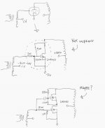
This is a stupidly simple mod I've used in modifiyng several NIVS (cheap chinese integrated) with very good results... The original "one tube for VA and phase splitter" version was inferior in all respects.
I am not saying that it is a perfect solution, but the sound improved dramatically with this topology.
Tha actually built version included grid and gate stopper resistors not shown on the picture.
I am not saying that it is a perfect solution, but the sound improved dramatically with this topology.
Tha actually built version included grid and gate stopper resistors not shown on the picture.
Attachments
- Home
- Amplifiers
- Tubes / Valves
- MosFET or other semiconductor substitute for cathodyne?