EUVL said:> http://www.epanorama.net/circuits/headphone_attenuator.html
They argue that you should put a 120ohm in series.
This is essentially an output attenuation.
You have to remember that the follower circuit has close to unity gain.
But I think you should ask Grey. I am not into headphones at all.
Patrick
I finally stole a moment and went to the link Patrick gave because I was curious about this 120 Ohm resistance at the output thing.
They're using the series resistance to pad down a hot output from an audio card. It's also implied, but not said directly, that they're using the resistance to lower the rolloff frequency due to a too-small coupling cap at the output of the card.
Given that we can use any value of coupling cap that we might wish (including none at all in the case of direct coupled circuits), I can't see that we need to worry about the low frequencies. And if it's too loud...turn it down. That may or may not be practical with a sound card, but it won't be any problem for an outboard headphone amp. My feeling is that I'd rather have a volume pot at the input than a series resistance at the output.
Grey
Hi Rudiger. The headphones are Beyerdynamics DT880 like these:
[showUID]=174&tx_sbproductdatabase_pi1[showUid][backPID]=105&cHash=efe58ee60e]DT 880's
I am not sure mine bears the 2005 Edition though.
The preamp I am using is the NS10 clone developed in Russ White's thread "My take on the Threshold NS10". It does a really good job in combination with this Mosfet follower headphone amp.
I dont know the rating of the heatsinks. Those used are recycled from some welding gear that blew up at work. I guess you could use something a bit smaller than those on the pictures, but I wouldnt make them a lot smaller. Euvl calculated the minimum size :
Steen")
[showUID]=174&tx_sbproductdatabase_pi1[showUid][backPID]=105&cHash=efe58ee60e]DT 880's
I am not sure mine bears the 2005 Edition though.
The preamp I am using is the NS10 clone developed in Russ White's thread "My take on the Threshold NS10". It does a really good job in combination with this Mosfet follower headphone amp.
I dont know the rating of the heatsinks. Those used are recycled from some welding gear that blew up at work. I guess you could use something a bit smaller than those on the pictures, but I wouldnt make them a lot smaller. Euvl calculated the minimum size :
You have approximately 20~25W to dissipate, so 1°C/W heatsink, or better.
Steen
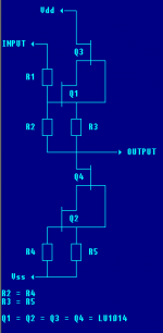
Here's a variation on a theme I've tried with high-impedance cans, adapted to LU1014s instead of 2SK170V. I think this is similar to what steenoe tried.

Vdd-Vss < 24V, of course.
The R1-R2 arrangement is based on some paper from Vishay, and should improve DC offset IIRC. I think R1=10K and R2=R4=1K should work, but I haven't got any LU's to play with (obtw, steen, I'm still waiting for a reply re those LU's )
)
R3/R5 can be 120 ohm for cans that are DIN compliant, lower otherwise. Cascoding limits the influence of the lower Ygs on this.
R4=R2 is just a rough approximation to match the influence of Igsx on gate voltage.
The LU's should be saturable down to 0.1Vds, and have -1Vgs on average IIRC, so strapping the cascode to the source should work fine. Not so good for my 2SK170's.
Vdd-Vss < 24V, of course.
The R1-R2 arrangement is based on some paper from Vishay, and should improve DC offset IIRC. I think R1=10K and R2=R4=1K should work, but I haven't got any LU's to play with (obtw, steen, I'm still waiting for a reply re those LU's
)R3/R5 can be 120 ohm for cans that are DIN compliant, lower otherwise. Cascoding limits the influence of the lower Ygs on this.
R4=R2 is just a rough approximation to match the influence of Igsx on gate voltage.
The LU's should be saturable down to 0.1Vds, and have -1Vgs on average IIRC, so strapping the cascode to the source should work fine. Not so good for my 2SK170's.
Attachments
I must have overlooked it, (or forgot) Please send me an email(obtw, steen, I'm still waiting for a reply re those LU's )
Steen
> The R1-R2 arrangement is based on some paper from Vishay, and should improve DC offset IIRC. I think R1=10K and R2=R4=1K should work. R3/R5 can be 120 ohm for cans that are DIN compliant, lower otherwise.
It would be interesting to see measurements of Id vs Vgs on both JFETs in your circuit when you load the output with say 200 ohm and drive the input with, say, a sine wave of 2.5Vrms, 1kHz.
Patrick
It would be interesting to see measurements of Id vs Vgs on both JFETs in your circuit when you load the output with say 200 ohm and drive the input with, say, a sine wave of 2.5Vrms, 1kHz.
Patrick
EUVL said:OK, I stick my neck out and fire the first shot.
Patrick
What does J511 refer to in teh schematic in post #11?
Sorry for the noobie question.
-David
J511 is a constant current diode of 4.7mA manufactured by, amongst others, Vishay. In combination with the Zener diode, it provides a constant voltage bias to the gate of the cascode MOSFET with good power supply ripple rejection.
You could also simply use two resistors for the same job.
Patrick
You could also simply use two resistors for the same job.
Patrick
What's the general consensus on benefits using these current diodes verses a resistor pair?
I noticed that Mouser sells the J511 for $1.91 each, certainly more than the cost of resistors. Just wondering if the added cost of using the diodes are are worth while.
Thanks!
-David
I noticed that Mouser sells the J511 for $1.91 each, certainly more than the cost of resistors. Just wondering if the added cost of using the diodes are are worth while.
Thanks!
-David
suiraMB said:
Vdd-Vss < 24V, of course.
I would suggest much lower rails. Assuming that the circuit might be driven to clipping, you're going to be perilously close to the voltage limit for the parts. They might take it...they might not...
Prepackaged current sources are convenient ways to provide small amounts of current. They're fairly quiet, too. Keep in mind that, like everything else, they are +- some arbitrary percentage. Depending on how exact you want your current, you may find yourself sorting them by hand.
If I'm going that route, I just pull out a small JFET and a resistor and build my own. (That's essentially all the Jxxx current sources are, anyway.)
Grey
GRollins said:I would suggest much lower rails. Assuming that the circuit might be driven to clipping, you're going to be perilously close to the voltage limit for the parts. They might take it...they might not...
Yes, I'd suggest lower rails too, for a different but related reason.
Even with a Vds of 0.1V, these devices can push a serious amount of current. Headphones rarely need a whole lot of voltage swing and current at the same time, and I got the idea that they were looking to drive low impedance cans, like the Grado ones.
Quite simply, hight voltage rails dissipate more for little real gain.
As for voltage limits, bear in mind that there should be at least 2V or so being burned in the resistors, and the cascodes suck up 4V or so (-2*Vgs each). Hence, at +/- 12V (what I intended as the upper limit), you're looking at 18Vds at clipping. Hardly anything to write home about with less than an amp of current and proper heatsinking, although not much point either.
But, yeah, being conservative is good, too.
Particularly if you go for cans that don't like the DIN-recommended output impedance, in which case I'd suggest switching the values. The Grado cans, at least, seem pretty flat, though, impedance-wise.
Prepackaged current sources are convenient ways to provide small amounts of current. They're fairly quiet, too. Keep in mind that, like everything else, they are +- some arbitrary percentage. Depending on how exact you want your current, you may find yourself sorting them by hand.
If I'm going that route, I just pull out a small JFET and a resistor and build my own. (That's essentially all the Jxxx current sources are, anyway.)
The circuit I suggested uses a current source that is identical to the follower, in order to get minimal offset when the components are matched, as well as similar operating characteristics, etc.
As for two-terminal JFET current sources, they're usually long-channel JFETs, whereas many audio JFETs are short-channel, with long-channel being preferable due to lower Ygs/Yfs ratio etc.. Also, I think the intrinsic resistance of the channel, not a diffused resistor, is what is offering the fixed saturation point.
That said, getting dual monolithic current sources is rare, so I prefer building them discretely and adjusting the currents with a pot to get minimum mismatch. Got some LS844 samples from LIS. Those had pretty nice matching. Can't wait to check out the LS843 (1mVgs diff, minimal temp drift, etc) in this regard. I'll have to beg nicely when I place the order for the LSK170's (waiting for the LSJ74's to become available first).
The purpose of using LU1014 in the original DAO Follower circuit with the fixed voltage cascode and the 3R source resistor is, despite the lower bias current, essentially the same as in ZV9, i.e. to make use of the triode characterisitics of this JFET to find a load line which is linear.
Therefore I am interested to see a load line based on Rsource 120R and a 1.xxV Vds cascode from another LU1014. You might find that the loadline is quite a bit different, and that you would lose quite a bit of transconductance of the amplifying JFET.
Not to mention of course that LU1014s are, as available in Europe, much more expensive than IRFP240 or IRFP044N.
Patrick
Hi EUVL
I can't believe I only just found this thread.
I have been seriously considering using mf F3 boards as a headphone amp.
However after seeing your design, I am not sure which would be the best way to go.
In your opinion which would sound better an F3 headphone amp or your DAO follower amp.
I would also appreciate any comments from Grey, or anyone else that has built the DAO follower amp.
Last edited:
Hello, EUVL
I have 2x15V 60VA transformer, do You think it will be OK with your DAO design? And what would be the minimum-descent capacitnce of filtering caps?
BTW I found LU1014 only on Ebay, and it's rather expensive, so it's important to know about matching this transistors... If it's necessary or not?
I have 2x15V 60VA transformer, do You think it will be OK with your DAO design? And what would be the minimum-descent capacitnce of filtering caps?
BTW I found LU1014 only on Ebay, and it's rather expensive, so it's important to know about matching this transistors... If it's necessary or not?
http://www.diyaudio.com/forums/pass...urce-follower-configurations.html#post1593654
This thread has all the answers to your questions.
Patrick
This thread has all the answers to your questions.
Patrick
- Status
- This old topic is closed. If you want to reopen this topic, contact a moderator using the "Report Post" button.
- Home
- Amplifiers
- Headphone Systems
- MOSFET follower headphone amplifier