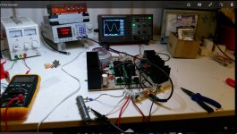
I put Banglas Amp in the lab to find out what happens. I told you that one channel is distorting, especially when the volume comes up. I build a dummy load as a voltgae devider so i can use my scope over a wider voltage range. The right channel is fine. The left channel has a trace of noise overlaid and when it goes into clipping there is some spikes visible. I shunted the input caps but that did not help. What can i do ?
Should i try to repair it ?
Should i try to repair it ?
Attachments
Last edited:
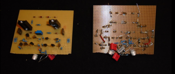
I put Banglas Amp in the lab to find out what happens. I told you that one channel is distorting, especially when the volume comes up. I build a dummy load as a voltgae devider so i can use my scope over a wider voltage range. The right channel is fine. The left channel has a trace of noise overlaid and when it goes into clipping there is some spikes visible. I shunted the input caps but that did not help. What can i do ?
Should i try to repair it ?
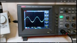
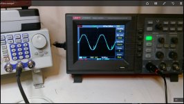
This is an HF oscillation - most likely the local one, happening in the bottom sholder of the output stage. Can you please drop a link to the exact schematic of the amplifier.
I don't recommend using the faulty channel with the speaker so far - at certain amplitude oscillation can fry the tweeter.
the 22n-bad part?
Hi Fellows.
Valery the board is Trrranigma- with Darlington Output- most parts like
Elvees original.
I try to place the pictures from thread first page:
http://www.diyaudio.com/forums/soli...tion-parts-accessories-beginner-friendly.html
http://www.diyaudio.com/forums/atta...es-beginner-friendly-circlophone-original.gif
http://www.diyaudio.com/forums/atta...accessories-beginner-friendly-bcv2-layout.jpg
Thank you for looking over here.
After your explaining words my thought- the 22n?
Joachim if you would like to repair it- i have done tin solder on copper tracks-
like timios on his work and all isolated with Plastic 70 Schutzlack- could stinking a bit. It's ok- i only can learn there.
Hope the amp will be on life after that.
Also hope that is to find the oscillating part, that you can enjoy music without
to destroy the speaker.
Cheers Bangla.
Elvee's compensation scheme is good. However, some faulty part may cause such issues.
For example, some time ago I used a cheap 50V-rated 100pF capacitor in a prototype for compensation in position, where it potentially sees up to 100V (push-pull VAS - one of two Miller caps) - just did not have a better one in hand at that time. In about half a year, at power on, it failed - went open, almost no capacitance - causing a pretty nasty oscillation. Replaced it with a good one - everything's fine again.
For example, some time ago I used a cheap 50V-rated 100pF capacitor in a prototype for compensation in position, where it potentially sees up to 100V (push-pull VAS - one of two Miller caps) - just did not have a better one in hand at that time. In about half a year, at power on, it failed - went open, almost no capacitance - causing a pretty nasty oscillation. Replaced it with a good one - everything's fine again.
Hi.
Supply voltage is 35VDC.
Capacitors: Styroflex- Banzai; 220n- MKP Q4 Audyn; FKP2 5%- Banzai/Schuro; Mica-
TubeTown. All new never soldered before.
Not sure- what i have used in place 330p-MosFet, 1n-Darlington?
I am interested to see wich is the faulty cap- the bad !
Cheers Bangla.
Supply voltage is 35VDC.
Capacitors: Styroflex- Banzai; 220n- MKP Q4 Audyn; FKP2 5%- Banzai/Schuro; Mica-
TubeTown. All new never soldered before.
Not sure- what i have used in place 330p-MosFet, 1n-Darlington?
I am interested to see wich is the faulty cap- the bad !
Cheers Bangla.
Hi there somewhere in Germany. I build the Elektor AXL amplifier 30 years ago and right now I made some modification to improve the sound quality again. First thing is the power supply. I used a Pi filter with 2 x 12000 uF and a 0,47 resistor in between. Also 2x 0,22 Ohm resistor between the rectifier and the first Capacitor. The input capacitors ( 3x 820nF) was replaced with a 4,7 uF Visaton MKP (polypropileen). Also a big improvement. Now I am designing a new PCB layout because I want to use two voltage regulators to make a very stable powersupply for the preamplifier using LM317 and LM337 (2x). The input capacitor (Viston MKP) I want to replace with a Clarity Cap ESA 2,7 uF or Mundorf Mcap MKP. End last but not least, the two power Mosfets (2SK134 and 2SK49) wil be replaced by ECF10N20 and ECF10P20. Tschüss.
update?
Hello Joachim, I just read through this thread and found it interesting, especially the amplifiers you decided to build, if you had time to finish all the amplifiers you had in mind to build I would be keen to hear your opinions how did they sound and perform.
Regards.
Hello Joachim, I just read through this thread and found it interesting, especially the amplifiers you decided to build, if you had time to finish all the amplifiers you had in mind to build I would be keen to hear your opinions how did they sound and perform.
Regards.
Hi Joachim.
fully clear- business first.
I have send you a private message here and ask for possibilities- what to do with my loan.
If no possible time to search failure- no problem, please send back, repaired or not, i'll sort out the bad channel.
I need psu and trafo for other amps.
Regards.
fully clear- business first.
I have send you a private message here and ask for possibilities- what to do with my loan.
If no possible time to search failure- no problem, please send back, repaired or not, i'll sort out the bad channel.
I need psu and trafo for other amps.
Regards.
Sorry, virtually no time for DIY. I have build the AXL partly but have not finished yet.
Thanks for your quick reply Joachim, I understand you are bussy, let the time have its own pace and the amp result will come when they are ready, good luck with all your other projects.
Damir has send boards so i will build his design.
Joachim, obviously you don't have the time to build that one too.
It's pity, this is really good amp.
BR Damir
Joachim, nice good news.
If your trusted person find time to find the failure i would be lucky too.
So we can learn a little.
One trusted person in Berlin, years back have give me help to bring a LatMos MJ Amp-
class A~ 500mA bias- to work. Wim de Haan has presented it on his page.
If not to complicated could you use my E-Mail?
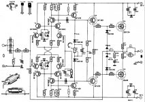
I will build Damirs amplifier later this year. On the other hand i would like to continue the AXL project. I need something for the forthcomming Frickelfest. It is the 10th anyversary.
I have already build the amp without output transistors.
So how whould a TMC version look ?
Here is the original circuit diagram.
I have already build the amp without output transistors.
So how whould a TMC version look ?
Here is the original circuit diagram.
Attachments
I will build Damirs amplifier later this year. On the other hand i would like to continue the AXL project. I need something for the forthcomming Frickelfest. It is the 10th anyversary.
I have already build the amp without output transistors.
So how whould a TMC version look ?
Here is the original circuit diagram.
Joachim, I think that you can build my amplifier faster (it's easier to populate ready made pcb than to finish that bird's nest and then you want TMC and that complicate the things). I would gladly simulate AXL amp with TMC or TPC, but I am kind of busy just now.
Damir
- Status
- This old topic is closed. If you want to reopen this topic, contact a moderator using the "Report Post" button.
- Home
- Amplifiers
- Solid State
- MosFet Class A amp, better compensation, TMC ?