QSC is a good example, but then you contradict yourself, saying "There s no gain...".
How would you achieve 100W @ 8 ohm with +/-15V_rails OpAmp, if the output stage would not provide additional voltage gain?
I contradict nothing, the op amp is supplied with +-15V and drive two transistors connected as common emitters, the collectors are connected to the full voltage rails through resistances, you can see that the power devices are also connected as common emitters, so the two low power transistors provide the voltage amplification along with the power trannies.
I ll simulate the thing out of curiosity, but that being said i wouldnt waste the Exicon in such a half baked design since this amount as common source configuration if it provide some voltage gain, a LME49830 driver is not that expensive and would provide much better perfs.
Right, LME49830 is excellent - fast, powerful, etc. However, Exicon lateral FETs are also good - input capacitance is not that high and pretty linear, so in the end difference in performance may be not that big (between LT1028 and LME49830). Interesting to see on a live prototype though

I contradict nothing, the op amp is supplied with +-15V and drive two transistors connected as common emitters, the collectors are connected to the full voltage rails through resistances, you can see that the power devices are also connected as common emitters, so the two low power transistors provide the voltage amplification along with the power trannies.
Right, so output stage provides the voltage gain, same as the one referenced in post #50 does.
Right, so output stage provides the voltage gain, same as the one referenced in post #50 does.
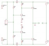
Yes but most of the gain is due to the drivers connected as common emitters, in post 50 not even the OS is in common emitter, here the topology of the QSC in respect of the supply voltages, you can see that it s not the same thing at all :
Attachments
Yes but most of the gain is due to the drivers connected as common emitters, in post 50 not even the OS is in common emitter, here the topology of the QSC in respect of the supply voltages, you can see that it s not the same thing at all :
That's ok - in QSC, the drivers are common emitters, the output devices are the followers. So, additional gain is provided with by the drivers. The output is at Q3, Q4 emitters.
In post #50 topology, there are no drivers, but the output MOSFETs are common source ones - they provide the voltage gain in this case (as well as driving enough current through the load). The output is at the MOSFETs' drains.
Last edited:
The output is at the MOSFETs' drains.
The output is at the sources actually, dont be fooled by the fact that the ground is floating...
The speaker is connected between the sources and the 0V (this later is used as hot point)..
The gates voltages in respect of the amp ground wont be at more than 18V, so the sources voltages in respect of the amp ground wont be at more than 18V, as such the amp ground wont lift more than 18V in respect of the 0V.
To lift the amp ground to more than 18V (in respect to the 0V) the gates need to be at more than 18V, no..??.
To reach full rail voltage the op amp should lift the gate voltage to 50V or so above the 0V, this way the amp ground will be lifted to 50V in respect of the 0V.
No. If you look carefully at the topology - floating power supply allows turning the OPS upside down. Imagine each power supply having the constant voltage and impedance close to zero.
The PSU's floating central tap is virtually connected to the drains, forming the output, referenced to ground.
The FETs are common source, providing the voltage gain. Just look at them the right way
Out of curiosity i simulated the circuit, so you are right after all, a few observation though, with a +-50V PSU the max output swing is +-40V with a NE5532, +-34V with the LT1028 and +-30V with TL071 and OPA627.
Quite possible that the op amp modelisations are faulty but not for several models...
I've built one of those rail-shifter amps long time ago (also with grounded source laterals, BUZ90x) and the outputs went as close to the rails as it gets, with light load. With heavy output current though, quite a bit of saturation drop will happen, those ECX10N20 have an Rds_on of about 1 Ohm which will raise even higher at low Vds. At high current Vgs also can get quite large, but most probably not the limiting factor with a +-15V opamp supply.
Yes it is.
The Board is a Terranigma for HexFet and Darlingtons- i like it- more compact without
Driver like BJT needed.
To build a BJT Circlophone is only a wish with SD1047 interesting to me.
http://www.diyaudio.com/forums/soli...tion-parts-accessories-beginner-friendly.html
Cheers.
The Board is a Terranigma for HexFet and Darlingtons- i like it- more compact without
Driver like BJT needed.
To build a BJT Circlophone is only a wish with SD1047 interesting to me.
http://www.diyaudio.com/forums/soli...tion-parts-accessories-beginner-friendly.html
Cheers.
The output is at the sources actually, dont be fooled by the fact that the ground is floating...
The speaker is connected between the sources and the 0V (this later is used as hot point)..
...
This is a misunderstanding. The ground is not floating, it is fixed.
The supply (and the midpoint of the supply) are floating. This is
not the same.
Simplification of the driver stage as seen here means that you need
independent supplies for each channel. But the driver supply can be
the same: it is grounded, not floating.
Amplifiers using these techniques are known for quite some time now.
(The circuit referred to was https://linearaudio.net/sites/linearaudio.net/files/May%2028-Figure%209%20-%20Full%20Amp.pdf)
I think i have made it that way.
Anyway, today i tried to listen to the Circlophone but i did not come far.
There is distortion in the right channel and the left one sounds louder.
I sounds like a mechanical distortion so i replaced the woofer with no success.
Tomorrow i will mount a new tweeter and see what happens.
Anyway, today i tried to listen to the Circlophone but i did not come far.
There is distortion in the right channel and the left one sounds louder.
I sounds like a mechanical distortion so i replaced the woofer with no success.
Tomorrow i will mount a new tweeter and see what happens.

- Status
- This old topic is closed. If you want to reopen this topic, contact a moderator using the "Report Post" button.
- Home
- Amplifiers
- Solid State
- MosFet Class A amp, better compensation, TMC ?