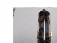
electrons hitting the glass, typically where there are holes or gaps in the anode, gradually turns the glass brown
Electrons (or rater ions) hitting the glass look lake mirror halos opposite cathode opening or anode holes. The dirt I am talking about is completely different kind - large irregular brown splotches. I haven't seen anything like this in other tube types.
Attachments
Last edited:
Wugh, ugly splotches!
I can just see the Ebay ad: Slightly used, low hours, original owner, already broken in, salvaged from a house fire with velvet gloves, mouse pee will clean off easily, audiophile treated, distortion burned off.
Looks like some kind of "creepage" damage along the glass surface where it has become conductive in the brown areas. Must be a high E field at the edge of the brown that is attracting damaging ions. Maybe the damage to the glass creates more ions too.
Last edited:
Wugh, ugly splotches!
I can just see the Ebay ad: Slightly used, low hours, original owner, already broken in, salvaged from a house fire with velvet gloves, mouse pee will clean off easily, audiophile treated, distortion burned off.
Looks like some kind of "creepage" damage along the glass surface where it has become conductive in the brown areas. Must be a high E field at the edge of the brown that is attracting damaging ions. Maybe the damage to the glass creates more ions too.
Funny though, I tested them and all test good. I am thinking it is some sort of re-depositioning of getter material.
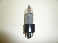
And also Russian 6P13S.
Russian tube 6P13S is somewhat different from EL36 (or Russian 6P31S) because it is well tolerated voltage at G2 up to ~ 400-450V!
Russian tube 6P13S is somewhat different from EL36 (or Russian 6P31S) because it is well tolerated voltage at G2 up to ~ 400-450V!
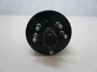
I stand corrected, 6P31S is closer to EL36 than 6P13S. Also, 6P13S has different pinout compared to EL36/6P31S.
I'm attached a photo I made some time ago, in this same thread (before splitting)Electrons (or rater ions) hitting the glass look lake mirror halos opposite cathode opening or anode holes. The dirt I am talking about is completely different kind - large irregular brown splotches. I haven't seen anything like this in other tube types.
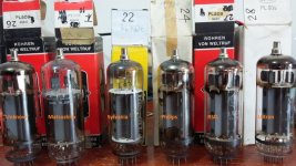
The Philips sample here have more splash, and from my PL509 collection, Philips tubes are notorious for this. RSD/Ultron have only the mica-aligned dirt or less spectacular dirt. Matsushitas and Sylvanias are less prone to dirt. Exceptions to rule sometimes occur.
Even Philips completely full of splotches measure perfectly and with very low g1 current (in nA magnitude for negative bias). Like sser2 said, these tubes are ok.
If we consider these tubes operating with near 7kV pulses in horizontal deflection duty, "things happens"
")
Attachments
Last edited:
Maybe for OTL fans the PL509 are indeed a 2A3 or 300B in their minds.........Yes, some sellers want insane money for EL509/519, as if they are 2A3 or something. .......
I don't know what the brown stuff is but I have seen several tubes that have it and they do seem to work fine. Coincidentally? they are all TV sweep tubes.
I have also seen some with the brown growth that didn't work so well, so the presence of the brown growth is no indicator of tube condition.
Tubes don't come from the factory that way, and I can't imagine something like that happening overnight, so I would tend to believe that you example has seen a good bit of use.
The Hangout
The best explanation I've heard about these brown spots seems to be the following: It is electrolysis, caused by stray electrons, that separates lead from the glass and deposits it to it's inner surface. Yes, TV tubes (sweeps, dampers) may be more prone to this, due to their higher working voltages, but I've also seen the same spots in older AF power tubes, such as EL 41's, that operate on 250Vdc.
German speaking guys may search for H.-T. Schmidt's site (Umleitung zur Homepage von H.-T. Schmidt) and find some good explanations.
Best regards!
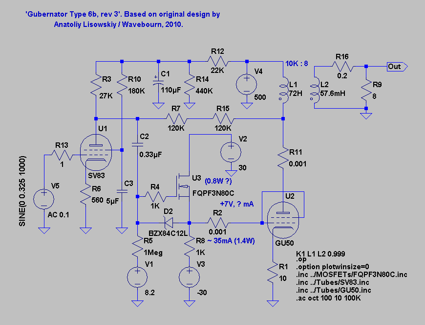
Talking of Anatoly (yes, he has many great ideas!) I seem to remember that his favourite tube, the GU50 fared pretty well in the crazy drive curves which was a bit surprising.
Not really a big surprise. If we could agree upon that the GU50 is a rather true copy of the old Telefunken LS50 and the FL152 (Telefunken, too) is the same tube, but in another envelope, we might have a look at their respective datasheets (http://www.mif.pg.gda.pl/homepages/frank/sheets/043/l/LS50.pdf and http://www.mif.pg.gda.pl/homepages/frank/sheets/118/e/EL152.pdf) and even find plate curves for combined control and screen grid drive (»Steuergitter und Schirmgitter verbunden« in German). Note that these curves represent direct connections between control and screen grids, not by a resistive divider.
Best regards!
The PL509/6KG6 tube has one of the highest glass temp specs I've seen in the TV Sweep tubes, 300 deg. C. Usually this is more like 220 deg. to 260 deg. This could have some connection to the splotch effects. Possibly a different glass composition used as well. The edges of the splotches have a fine structure, a little reminiscent of "Kirlian photography". A strong electric field involved at the edges I think. Which would occur if the brown area were somewhat conductive, concentrating the E field gradients at the edges.
The GU50 and related tubes have an internal Mu of around 6, so they are midway between TV Sweeps (3 to 4) and 6L6 types (8). The value of the Twin/Crazy drive Rg2g1 resistor has to increase in that case, with the higher Vg2, so the transconductance linearization for the assembly is occurring at a lower net gm. (otherwise grid 1 would be getting over-heated in pos. territory) This means these tubes are going to require more drive signal V. 6L6 types becoming a bit impractical. (like 6L6 driving an 807)
Connecting grid 1 and grid 2 together is a mystery to me. This would effectively be turning the tube into a beam triode like 6JK5 and similar tubes. Really high plate V would be needed to get any conduction, unless the grids are going positive. Which is limited before grid 1 starts sucking up all the current.
..
Last edited:
Which is limited before grid 1 starts sucking up all the current.
Hence the resistor in those early 807 / 6L6 "high Mu triode" schematics.
I remember seeing a datasheet for a transmitting pentode years ago that had data for G1 connected to G2. They called it High Mu Triode mode.
I can't find it now. I was looking up all the oddball tubes from the WWII era collection that I got in the lot of 100,000 tubes for free about 15 years ago.
Obviously I decided not to keep those tubes, or the datasheet would still be on my PC. Many tubes were not kept simply because I only had one or two, or an impractical OPT would be needed to use them. This is often the case with HV transmitting tubes.
3D21 or its relative the 7403.
Wasn't them. I kept those. Don't have enough of them to risk building an amp though. I have 4. If one blows.....game over. If I come up with a few more, I can see a 50+ WPC triode amp in my future.
I believe it was one of those tall transmitting tubes about the size of an 828, but it was a long time ago and I had a LOT of tubes to sort.
The PL509/6KG6 tube has one of the highest glass temp specs I've seen in the TV Sweep tubes, 300 deg. C. Usually this is more like 220 deg. to 260 deg...
This is probably the reason why Svetlana increased envelope diameter from 40 to 46 mm when designing its version of EL519, the 6P45S. Maximum temperature went down from 300 to 280 degrees centigrade. Svetlana also designed special ceramic Magnoval sockets for these tubes.
These are very high temperatures for glass, so special glass had to be used. I guess it was borosilicate glass, which combines high strength, low thermal expansion, and high working temperature.
Last edited:
I remember those. That was an intermediate generation of TVs with most of SS active components but still a couple tubes one of which sitting in that magnoval socket, it became a common curse of that model line.Svetlana also designed special ceramic Magnoval sockets for these tubes.
The GU50 and related tubes have an internal Mu of around 6, so they are midway between TV Sweeps (3 to 4) and 6L6 types (8). The value of the Twin/Crazy drive Rg2g1 resistor has to increase in that case, with the higher Vg2, so the transconductance linearization for the assembly is occurring at a lower net gm. (otherwise grid 1 would be getting over-heated in pos. territory) This means these tubes are going to require more drive signal V. 6L6 types becoming a bit impractical. (like 6L6 driving an 807)
Connecting grid 1 and grid 2 together is a mystery to me. This would effectively be turning the tube into a beam triode like 6JK5 and similar tubes. Really high plate V would be needed to get any conduction, unless the grids are going positive. Which is limited before grid 1 starts sucking up all the current.
..
http://www.wavebourn.com/forum/download.php?id=491&f=7
- Status
- This old topic is closed. If you want to reopen this topic, contact a moderator using the "Report Post" button.
- Home
- Amplifiers
- Tubes / Valves
- More Ruminations on Screen Drive/Crazy Drive