807 crazy drive amplifier
I found this schematic - STC Zero Bias amplifier. It uses the mixed g1g2 drive 807 PP stage, with 22 K resistor between grids, but without g1 to cathode resistors. As shown, it reportedly has zero bias and operates in Class B2. It is possible that there is some small bias current to minimize crossover distortion. The beefy 6L6G (why not 807?) pentode driver with B+ of 600 V is transformer-coupled to the power stage. Note the insane driving voltage and power. It seems like output stage gain is close to unity, and low driver distortion at high output voltage is achieved through the combination of high plate voltage and inductive load.
From the absence of global negative feedback, it seems like this amplifier has low distortion figure.
So, Class B operation is possible with crazy drive...
The link to the schematic:
100 Amplifiers – Part 1 , 1916 – 45 | Lilienthal Engineering
Attachments
Just recently contemplated on this... here is one more for ya (I think this deserves a dedicated thread, if moderators could split it):
An externally hosted image should be here but it was not working when we last tested it.
I first ran across this circuit at least 25 years ago. I think the schematic I saw used 10K resistors for the grid. I built one back then with the idea of making a big guitar amp, but the distortion, especially at low volumes was too much. I think this design was intended for use as a transmitter modulator or a stadium PA, some speech application that was usually run at a high power output level where efficiency was more important than fidelity.
The output stage does require more driving voltage than a typical G1 only driven stage, but this is the case with any screen driven amp, but there is still voltage gain. Any G2 drive scheme will always draw current too, so drive power will be needed. The 807 needs a lot of drive voltage on G2, so it takes more power than the typical sweep tube (which wasn't available when this schematic was drawn).
The output stage does require more driving voltage than a typical G1 only driven stage, but this is the case with any screen driven amp, but there is still voltage gain. Any G2 drive scheme will always draw current too, so drive power will be needed. The 807 needs a lot of drive voltage on G2, so it takes more power than the typical sweep tube (which wasn't available when this schematic was drawn).
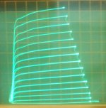
I have enough grid V sweep range now to do a half way decent curve trace of the 1625/807 tube using a 20K Ohm grid2 to grid1 resistor. (no grid1 to cathode resistor here) Similar to the STC schematic sser2 posted.
1625/807 STC drive, similar to Twin/Crazy drive:
20 mA/div Vert., 50 V /div Horiz., +12V steps on grid2 (with 20K to grid 1)
Looks like they knew how it worked back then. This probably never caught on due to their choice of an 807 tube (with HV grid2). Nobody wanted to use a 6L6 to drive an 807.
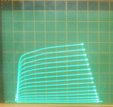
2nd pic is the 1625 with grid2 drive only.
Same 20 mA/div Vert., 50 V/div Horiz. and +12V steps on grid 2 only.
Less plate current output without the grid1 and 20K, and more gm variation.
1625/807 STC drive, similar to Twin/Crazy drive:
20 mA/div Vert., 50 V /div Horiz., +12V steps on grid2 (with 20K to grid 1)
Looks like they knew how it worked back then. This probably never caught on due to their choice of an 807 tube (with HV grid2). Nobody wanted to use a 6L6 to drive an 807.
2nd pic is the 1625 with grid2 drive only.
Same 20 mA/div Vert., 50 V/div Horiz. and +12V steps on grid 2 only.
Less plate current output without the grid1 and 20K, and more gm variation.
Attachments
Last edited:
The two 1625 curve sets posted above both start at 0V on grid2 and go up to +168V on grid2 in 12V steps. So there is not some conduction gap, like for class C. One will need relatively little positive grid bias for a low crossover dist. idle current setting in P-P class aB, due to the near constant gm.
The extra grid1 to cathode resistor, Rg1k, used up till now for Twin/Crazy drive does not seem to help much for the 1625/807 tube. But it does seem to be helpful for many of the LV grid2 TV Sweep tubes (Rg1k can reduce anomalously high gm in the low current range, probably due to some internal thermal-electric grid1 V offset preventing grid1 current in the low drive range). I would just call Rg1k a variable value to be optimized per tube type. Could be infinite or very high value for some tubes.
The extra grid1 to cathode resistor, Rg1k, used up till now for Twin/Crazy drive does not seem to help much for the 1625/807 tube. But it does seem to be helpful for many of the LV grid2 TV Sweep tubes (Rg1k can reduce anomalously high gm in the low current range, probably due to some internal thermal-electric grid1 V offset preventing grid1 current in the low drive range). I would just call Rg1k a variable value to be optimized per tube type. Could be infinite or very high value for some tubes.
Last edited:
... the distortion, especially at low volumes was too much.
Courtesy of Smoking-amp, we know the reason: while linearity over broad range of grid voltages is excellent, the area of low voltages is not linear. If I remember correct, this was also true for other TV sweep tubes (BTW, 807 has been used as a TV sweep tube). This might seem like fatal blow to the idea of using crazy drive in hi-fi amplifiers, where the first watt matters most.
But what about Class A crazy drive? The stage can be easily biased to the midpoint grid voltage by adding a resistor to B+.
Mickeystan got good results with his 6DQ5 P-P Twin/Crazy drive amplifier with some moderate idle current.
A SE Twin/Crazy setup should work well too, of course. Or class A P-P should be quite linear. Those would lose the nice efficiency usually seen with Twin or g2 drives in class aB P-P. The output Z needs to be lowered in any case, SE or P-P.
I think you just have to use a little more than -ZERO- Volt grid2 bias (as the STC amp used). And Rg1k (the extra resistor from grid 1 to cathode) can tune out most any gm anomaly down at low signal drive. What is not optimal about the STC amp is the 807 output tubes, with zero bias. Needs LV screen grid tubes with optimized idle current.
Last edited:
If I remember correct, this was also true for other TV sweep tubes (BTW, 807 has been used as a TV sweep tube).
True sweep tubes have much higher Gm on the screen grid than the 6L6 types. The 807 was a derivative of the 6L6GA, and so was the TV horizontal sweep tube 6BG6GA. The internals of old 6BG6's are exactly the same as a 6L6GA, while 807's of the same vintage are 6L6GA's with added shielding around the bottom of the internals for RF use. I believe that there were more vendors for the 807 than just about any military part used in WWII. After the war when the demand for 807's and 6BG6's dwindled there was some creative glass stuffing done by some tube suppliers. I have seen 807's with 6L6GA, 6L6GB and 6L6GC guts, and 6BG6's with 6L6GA, 6L6GB and 7027A guts.
No matter which 6L6 type guts are in the glass, their behavior will be different than any true TV sweep tube.
Mickeystan got good results with his 6DQ5 P-P Twin/Crazy drive amplifier with some moderate idle current.
Good to know this is practical.
A SE Twin/Crazy setup should work well too, of course. Or class A P-P should be quite linear. Those would lose the nice efficiency usually seen with Twin or g2 drives in class aB P-P. The output Z needs to be lowered in any case, SE or P-P.
Well, Class A is not done for efficiency. From your EL509 plate curves, I figured 400 Ohms optimal load for Class A SE, or 800 Ohms CT for PP. 130 V on plate, 230 mA idle current per tube. About 16 W output power PP.
I think you just have to use a little more than -ZERO- Volt grid2 bias (as the STC amp used). And Rg1k (the extra resistor from grid 1 to cathode) can tune out most any gm anomaly down at low signal drive. What is not optimal about the STC amp is the 807 output tubes, with zero bias. Needs LV screen grid tubes with optimized idle current.
Do I get it right that 6L6 is not optimal for crazy drive because of very low amplification factor?
True sweep tubes have much higher Gm on the screen grid than the 6L6 types. The 807 was a derivative of the 6L6GA, and so was the TV horizontal sweep tube 6BG6GA. The internals of old 6BG6's are exactly the same as a 6L6GA, while 807's of the same vintage are 6L6GA's with added shielding around the bottom of the internals for RF use. I believe that there were more vendors for the 807 than just about any military part used in WWII. After the war when the demand for 807's and 6BG6's dwindled there was some creative glass stuffing done by some tube suppliers. I have seen 807's with 6L6GA, 6L6GB and 6L6GC guts, and 6BG6's with 6L6GA, 6L6GB and 7027A guts.
No matter which 6L6 type guts are in the glass, their behavior will be different than any true TV sweep tube.
Yes, from what I've read here, "true" sweep tubes have tighter spacing between g1 and g2, which means higher g1g2 mu and lower Ug2 rating, compared to typical audio or RF power pentodes. They also have aligned grids to lower g2 current. But there could be some exceptions. EL38 is a purpose TV sweep tube with g2 rating of 400V.
Thanks for explaining about 807 tubes. I also noticed a lot of variation in their internal construction. In my ignorance I thought they are all 6L6 with anode cap.
The critical factor for practical g2 drive or Crazy/Twin drive is the transconductance of grid 2. (high gm2 best) You just want reduced grid2 drive voltage basically.
gm2 = gm1 / Mu
This will generally show up in datasheets as a low max g2 voltage spec or a low g2/g1 Mu. The 6L6 or 807 etc
-can- be run in g2 or Twin drive, but it takes one Hell of a driver to do it (like another 6L6) plus HV B+ for the driver. Another way to tell is by how much knee current can be pulled from a tube with say +150V on g2. (table below of TV Sweep tube, knee currents at +150V on grid2, Mu factors) The higher in the list, the better.
The g2/g1 Mu of 6L6 and similar KT tubes is around 8. While the more practical TV Sweep tubes have a g2/g1 Mu of around 3 or 4. (so require about half the grid2 drive signal Volts of the 6L6 types)
List of knee currents for g2 = 150 V, g1 = 0 V, Vp = 60 to 80 V
<tube> <Watts> <mA knee@150Vg2> <gm1> <g2/g1 Mu> <maxDCmA> <registered by> <date>
6LF6 40W 1144mA@150V 15K@125mA Mu3 500mADC Amperex 1968
6KG6/EL509 34W 1135mA@150V 13K@150mA Mu3.2 500mADC Amperex 1965
6MC6 33W 1130mA@150V 14K@125mA Mu4 400mADC RCA (6LX6 clone) 1972
13E1 90W(absmax) 1120mA@150V 35K@500mA Mu4.5 800mADC AEI 1961
6MH6 38.3W 1100mA@150V 14K@125mA Mu4 500mADC GE (up-rated 6LX6,6KD6,26HU5) 1972
6MB6 38W 1085mA@150V 14K@110mA Mu3.5 400mADC Sylvania 1971
6LR6 30W 1085mA@150V 16K@140mA Mu3.5 375mADC Sylvania 1968
6LX6/6KD6/26HU5 33W 1080mA@150V 14K@125mA Mu4 400mADC GE 1969/1965/1969
6LW6 40W 1050mA@150V 12K@125mA Mu3.7 400mADC GE 1971
6KN6 30W 1050mA@150V 16K@100mA Mu4.5 400mADC Sylvania 1965 (later versions are 6KD6)
6LZ6 30W 940mA@150V 11K@140mA Mu3 350mADC RCA 1971
6LB6/A 30W/35W 825mA@150V 13.4K@105mA Mu4 315mADC GE 1967
6JE6C/6JS6C 30W 789mA@150V 10.5K@130mA Mu3 350mADC Sylvania 68/69
6JE6 24W 762mA@150V 9.6K@115mA Mu3 315mADC RCA 1962
6JS6/6HF5 28W 749mA@150V 11.5K@130mA Mu3 315mADC GE 1964/1963
6MJ6 30W 740mA@150V 11K@100mA Mu3.6 350mADC RCA 1973
6LG6 28W 740mA@150V 11.5K@90mA Mu3.6 315mADC GE 1967
6LQ6 30W 715mA@150V 7.5K@95mA Mu3 350mADC RCA 1967
6ME6 30W 700mA@150V 9.6@130mA Mu3.5 350mADC RCA 1971
6DQ5 24W 690mA@150V 10.5K@110mA Mu3.3 315mADC RCA 1957
6JF6/6JG6 17W 660mA@150V 10K@80mA Mu4.1 275mADC RCA 1965/1964
6KM6 20W 630mA@150V 9.5K@80mA Mu4 275mADC RCA 1965
6HD5/6HJ5 24W 630mA@150V 10K@80mA Mu4.2 280mADC Raytheon 1962/1963
6JR6/6JU6 17W 600mA@150V 7K@45mA Mu4.7 275mADC RCA 1968/1966
6JZ6/21HB5A 18W 560mA@150V 9K@46mA Mu4.8 230mADC GE 1966/1964
12HE7 10-15W 540mA@150V 8.8K@60mA Mu4.2 200mADC GE (15W if damper disabled) 1964
6CL5 25W 514mA@150V 6.5K@90mA Mu3 240mADC Sylvania 1955
6GB5/29KQ6/EL500 17W 500mA@150V 13K@100mA Mu5.1 275mADC Amperex 1961/Matsushita 1959/Philips 1961?
6KV6/A 20-28W 488/610mA@150V 6K@40mA Mu4 275mADC RCA (re-rated 6KM6?) 1967/1969
6HB5/6GY5/21JV6/6KE6/16KA6 18W 475mA@150V 9.1K@50mA Mu4.7 230mADC GE/GE/GE/Ray/Tung 1962/1962/1965/1965/1964
6EX6 22W 460mA@150V 7.7K@67mA Mu4.2 220mADC Raytheon (up-rated 6CD6) 1959
6CB5/A 23W 440mA@150V 8.8K@90mA Mu3.8 240mADC RCA 1954/1956
6CD6/GA 15/20W 422mA@150V 7.7K@75mA Mu3.9 200mADC RCA/GE 1949/1954
6GT5/6GJ5/6JT6/6JB6/6GW6 17.5W 380mA@150V 7.1K@70mA Mu4.4 175mADC RCA 1961/1961/1964/1962/1961
6GE5 17.5W 350mA@150V 7.3K@65mA Mu4.4 175mADC GE 1961
6GF5 9W 345mA@150V 4.7K@34mA Mu4.2 160mADC GE 1961
6JM6/6JN6/6FW5/6GC6 17.5W 340mA@150V 7.3K@70mA Mu4.4 175mADC GE 1964/1964/1960/1960
6DQ6B/6GV5 17.5W/18W 330mA@150V 7.3K@65mA Mu4.4 175mADC GE 1959/1962
6DQ6/A 18W 280mA@150V 6.6K@55mA Mu4.1 120/155mADC CBS/RCA 1955/1956
6JA5/10JA5 19W 276mA@150V 10.3K@95mA Mu5.5 110mADC GE 1971
6LU8/6LR8//6MY8 14//16W 265mA@150V 9.3K@56mA Mu6.5 75mADC Sylvania 1964/1964//1970(Toshiba)
6AV5/GA///6BQ6/GA 11W 255ma@150V 5.9K@57mA Mu4.3 110mADC CBS/GE 1949/1955 /// CBS/Syl 1949/1953
KT120 60W 221ma@150V 190mADC
KT90 50W 220mA@150V
6Y6G/GT/GA 12.5W 200mA@150V Ray 1937/KenRad 1939/Syl 1954
6550A 35W/42W 190mA@150V 11K@140mA 190mADC
6W6GT 10W 185mA@150V 8K@46mA Mu6.2 65mADC CBS 1939
KT88 35W 170mA@150V 175mADC
6CA7/EL34 25W 107mA@150V 11K@100mA Mu10.5 150mADC Philips 1952
6JC5 19W 80mA@150V 4.1K@43mA Mu7 75mADC Sylvania 1971
6L6/G/GA/GB/GC 30W 77mA@150V 4.7K@40mA Mu8 110mADC RCA 1936/Ray 1936/Syl 1943/Syl 1954/GE 1958
6HB6 10W 70mA@150V 20K@40mA Mu33 60mADC Raytheon 1961
6GK6 13.2W 65mA@150V 11.3K@48mA Mu19 65mADC CBS 1959
6BQ5/EL84 12W 65mA@150V 11.3K@48mA Mu19.5 65mADC Rogers 1956
6V6G/GT 14W 45mA@150V 4.1K@45mA Mu9.8 40mADC KenRad 1936/CBS 1939
Last edited:
copied into a word document for easy reference, thanks smoking amp...
The critical factor for practical g2 drive or Crazy/Twin drive is the transconductance of grid 2. (high gm2 best) You just want reduced grid2 drive voltage basically.
gm2 = gm1 / Mu
This will generally show up in datasheets as a low max g2 voltage spec or a low g2/g1 Mu. The 6L6 or 807 etc
-can- be run in g2 or Twin drive, but it takes one Hell of a driver to do it (like another 6L6) plus HV B+ for the driver. Another way to tell is by how much knee current can be pulled from a tube with say +150V on g2. (table below of TV Sweep tube, knee currents at +150V on grid2, Mu factors) The higher in the list, the better.
The g2/g1 Mu of 6L6 and similar KT tubes is around 8. While the more practical TV Sweep tubes have a g2/g1 Mu of around 3 or 4. (so require about half the grid2 drive signal Volts of the 6L6 types)
List of knee currents for g2 = 150 V, g1 = 0 V, Vp = 60 to 80 V
<tube> <Watts> <mA knee@150Vg2> <gm1> <g2/g1 Mu> <maxDCmA> <registered by> <date>
6LF6 40W 1144mA@150V 15K@125mA Mu3 500mADC Amperex 1968
6KG6/EL509 34W 1135mA@150V 13K@150mA Mu3.2 500mADC Amperex 1965
6MC6 33W 1130mA@150V 14K@125mA Mu4 400mADC RCA (6LX6 clone) 1972
13E1 90W(absmax) 1120mA@150V 35K@500mA Mu4.5 800mADC AEI 1961
6MH6 38.3W 1100mA@150V 14K@125mA Mu4 500mADC GE (up-rated 6LX6,6KD6,26HU5) 1972
6MB6 38W 1085mA@150V 14K@110mA Mu3.5 400mADC Sylvania 1971
6LR6 30W 1085mA@150V 16K@140mA Mu3.5 375mADC Sylvania 1968
6LX6/6KD6/26HU5 33W 1080mA@150V 14K@125mA Mu4 400mADC GE 1969/1965/1969
6LW6 40W 1050mA@150V 12K@125mA Mu3.7 400mADC GE 1971
6KN6 30W 1050mA@150V 16K@100mA Mu4.5 400mADC Sylvania 1965 (later versions are 6KD6)
6LZ6 30W 940mA@150V 11K@140mA Mu3 350mADC RCA 1971
6LB6/A 30W/35W 825mA@150V 13.4K@105mA Mu4 315mADC GE 1967
6JE6C/6JS6C 30W 789mA@150V 10.5K@130mA Mu3 350mADC Sylvania 68/69
6JE6 24W 762mA@150V 9.6K@115mA Mu3 315mADC RCA 1962
6JS6/6HF5 28W 749mA@150V 11.5K@130mA Mu3 315mADC GE 1964/1963
6MJ6 30W 740mA@150V 11K@100mA Mu3.6 350mADC RCA 1973
6LG6 28W 740mA@150V 11.5K@90mA Mu3.6 315mADC GE 1967
6LQ6 30W 715mA@150V 7.5K@95mA Mu3 350mADC RCA 1967
6ME6 30W 700mA@150V 9.6@130mA Mu3.5 350mADC RCA 1971
6DQ5 24W 690mA@150V 10.5K@110mA Mu3.3 315mADC RCA 1957
6JF6/6JG6 17W 660mA@150V 10K@80mA Mu4.1 275mADC RCA 1965/1964
6KM6 20W 630mA@150V 9.5K@80mA Mu4 275mADC RCA 1965
6HD5/6HJ5 24W 630mA@150V 10K@80mA Mu4.2 280mADC Raytheon 1962/1963
6JR6/6JU6 17W 600mA@150V 7K@45mA Mu4.7 275mADC RCA 1968/1966
6JZ6/21HB5A 18W 560mA@150V 9K@46mA Mu4.8 230mADC GE 1966/1964
12HE7 10-15W 540mA@150V 8.8K@60mA Mu4.2 200mADC GE (15W if damper disabled) 1964
6CL5 25W 514mA@150V 6.5K@90mA Mu3 240mADC Sylvania 1955
6GB5/29KQ6/EL500 17W 500mA@150V 13K@100mA Mu5.1 275mADC Amperex 1961/Matsushita 1959/Philips 1961?
6KV6/A 20-28W 488/610mA@150V 6K@40mA Mu4 275mADC RCA (re-rated 6KM6?) 1967/1969
6HB5/6GY5/21JV6/6KE6/16KA6 18W 475mA@150V 9.1K@50mA Mu4.7 230mADC GE/GE/GE/Ray/Tung 1962/1962/1965/1965/1964
6EX6 22W 460mA@150V 7.7K@67mA Mu4.2 220mADC Raytheon (up-rated 6CD6) 1959
6CB5/A 23W 440mA@150V 8.8K@90mA Mu3.8 240mADC RCA 1954/1956
6CD6/GA 15/20W 422mA@150V 7.7K@75mA Mu3.9 200mADC RCA/GE 1949/1954
6GT5/6GJ5/6JT6/6JB6/6GW6 17.5W 380mA@150V 7.1K@70mA Mu4.4 175mADC RCA 1961/1961/1964/1962/1961
6GE5 17.5W 350mA@150V 7.3K@65mA Mu4.4 175mADC GE 1961
6GF5 9W 345mA@150V 4.7K@34mA Mu4.2 160mADC GE 1961
6JM6/6JN6/6FW5/6GC6 17.5W 340mA@150V 7.3K@70mA Mu4.4 175mADC GE 1964/1964/1960/1960
6DQ6B/6GV5 17.5W/18W 330mA@150V 7.3K@65mA Mu4.4 175mADC GE 1959/1962
6DQ6/A 18W 280mA@150V 6.6K@55mA Mu4.1 120/155mADC CBS/RCA 1955/1956
6JA5/10JA5 19W 276mA@150V 10.3K@95mA Mu5.5 110mADC GE 1971
6LU8/6LR8//6MY8 14//16W 265mA@150V 9.3K@56mA Mu6.5 75mADC Sylvania 1964/1964//1970(Toshiba)
6AV5/GA///6BQ6/GA 11W 255ma@150V 5.9K@57mA Mu4.3 110mADC CBS/GE 1949/1955 /// CBS/Syl 1949/1953
KT120 60W 221ma@150V 190mADC
KT90 50W 220mA@150V
6Y6G/GT/GA 12.5W 200mA@150V Ray 1937/KenRad 1939/Syl 1954
6550A 35W/42W 190mA@150V 11K@140mA 190mADC
6W6GT 10W 185mA@150V 8K@46mA Mu6.2 65mADC CBS 1939
KT88 35W 170mA@150V 175mADC
6CA7/EL34 25W 107mA@150V 11K@100mA Mu10.5 150mADC Philips 1952
6JC5 19W 80mA@150V 4.1K@43mA Mu7 75mADC Sylvania 1971
6L6/G/GA/GB/GC 30W 77mA@150V 4.7K@40mA Mu8 110mADC RCA 1936/Ray 1936/Syl 1943/Syl 1954/GE 1958
6HB6 10W 70mA@150V 20K@40mA Mu33 60mADC Raytheon 1961
6GK6 13.2W 65mA@150V 11.3K@48mA Mu19 65mADC CBS 1959
6BQ5/EL84 12W 65mA@150V 11.3K@48mA Mu19.5 65mADC Rogers 1956
6V6G/GT 14W 45mA@150V 4.1K@45mA Mu9.8 40mADC KenRad 1936/CBS 1939
smoking-amp, wish you can include the 4d32 in your list...
Should be pretty low on the list with g2g1 mu of 10. Great tube though. You may also look at 4E27, even more extreme.
The critical factor for practical g2 drive or Crazy/Twin drive is the transconductance of grid 2. (high gm2 best) You just want reduced grid2 drive voltage basically.
gm2 = gm1 / Mu
This will generally show up in datasheets as a low max g2 voltage spec or a low g2/g1 Mu. The 6L6 or 807 etc
-can- be run in g2 or Twin drive, but it takes one Hell of a driver to do it (like another 6L6) plus HV B+ for the driver. Another way to tell is by how much knee current can be pulled from a tube with say +150V on g2. (table below of TV Sweep tube, knee currents at +150V on grid2, Mu factors) The higher in the list, the better.
The g2/g1 Mu of 6L6 and similar KT tubes is around 8. While the more practical TV Sweep tubes have a g2/g1 Mu of around 3 or 4. (so require about half the grid2 drive signal Volts of the 6L6 types)
List of knee currents for g2 = 150 V, g1 = 0 V, Vp = 60 to 80 V
<tube> <Watts> <mA knee@150Vg2> <gm1> <g2/g1 Mu> <maxDCmA> <registered by> <date>
6LF6 40W 1144mA@150V 15K@125mA Mu3 500mADC Amperex 1968
6KG6/EL509 34W 1135mA@150V 13K@150mA Mu3.2 500mADC Amperex 1965
6MC6 33W 1130mA@150V 14K@125mA Mu4 400mADC RCA (6LX6 clone) 1972
13E1 90W(absmax) 1120mA@150V 35K@500mA Mu4.5 800mADC AEI 1961
6MH6 38.3W 1100mA@150V 14K@125mA Mu4 500mADC GE (up-rated 6LX6,6KD6,26HU5) 1972
6MB6 38W 1085mA@150V 14K@110mA Mu3.5 400mADC Sylvania 1971
6LR6 30W 1085mA@150V 16K@140mA Mu3.5 375mADC Sylvania 1968
6LX6/6KD6/26HU5 33W 1080mA@150V 14K@125mA Mu4 400mADC GE 1969/1965/1969
6LW6 40W 1050mA@150V 12K@125mA Mu3.7 400mADC GE 1971
6KN6 30W 1050mA@150V 16K@100mA Mu4.5 400mADC Sylvania 1965 (later versions are 6KD6)
6LZ6 30W 940mA@150V 11K@140mA Mu3 350mADC RCA 1971
6LB6/A 30W/35W 825mA@150V 13.4K@105mA Mu4 315mADC GE 1967
6JE6C/6JS6C 30W 789mA@150V 10.5K@130mA Mu3 350mADC Sylvania 68/69
6JE6 24W 762mA@150V 9.6K@115mA Mu3 315mADC RCA 1962
6JS6/6HF5 28W 749mA@150V 11.5K@130mA Mu3 315mADC GE 1964/1963
6MJ6 30W 740mA@150V 11K@100mA Mu3.6 350mADC RCA 1973
6LG6 28W 740mA@150V 11.5K@90mA Mu3.6 315mADC GE 1967
6LQ6 30W 715mA@150V 7.5K@95mA Mu3 350mADC RCA 1967
6ME6 30W 700mA@150V 9.6@130mA Mu3.5 350mADC RCA 1971
6DQ5 24W 690mA@150V 10.5K@110mA Mu3.3 315mADC RCA 1957
6JF6/6JG6 17W 660mA@150V 10K@80mA Mu4.1 275mADC RCA 1965/1964
6KM6 20W 630mA@150V 9.5K@80mA Mu4 275mADC RCA 1965
6HD5/6HJ5 24W 630mA@150V 10K@80mA Mu4.2 280mADC Raytheon 1962/1963
6JR6/6JU6 17W 600mA@150V 7K@45mA Mu4.7 275mADC RCA 1968/1966
6JZ6/21HB5A 18W 560mA@150V 9K@46mA Mu4.8 230mADC GE 1966/1964
12HE7 10-15W 540mA@150V 8.8K@60mA Mu4.2 200mADC GE (15W if damper disabled) 1964
6CL5 25W 514mA@150V 6.5K@90mA Mu3 240mADC Sylvania 1955
6GB5/29KQ6/EL500 17W 500mA@150V 13K@100mA Mu5.1 275mADC Amperex 1961/Matsushita 1959/Philips 1961?
6KV6/A 20-28W 488/610mA@150V 6K@40mA Mu4 275mADC RCA (re-rated 6KM6?) 1967/1969
6HB5/6GY5/21JV6/6KE6/16KA6 18W 475mA@150V 9.1K@50mA Mu4.7 230mADC GE/GE/GE/Ray/Tung 1962/1962/1965/1965/1964
6EX6 22W 460mA@150V 7.7K@67mA Mu4.2 220mADC Raytheon (up-rated 6CD6) 1959
6CB5/A 23W 440mA@150V 8.8K@90mA Mu3.8 240mADC RCA 1954/1956
6CD6/GA 15/20W 422mA@150V 7.7K@75mA Mu3.9 200mADC RCA/GE 1949/1954
6GT5/6GJ5/6JT6/6JB6/6GW6 17.5W 380mA@150V 7.1K@70mA Mu4.4 175mADC RCA 1961/1961/1964/1962/1961
6GE5 17.5W 350mA@150V 7.3K@65mA Mu4.4 175mADC GE 1961
6GF5 9W 345mA@150V 4.7K@34mA Mu4.2 160mADC GE 1961
6JM6/6JN6/6FW5/6GC6 17.5W 340mA@150V 7.3K@70mA Mu4.4 175mADC GE 1964/1964/1960/1960
6DQ6B/6GV5 17.5W/18W 330mA@150V 7.3K@65mA Mu4.4 175mADC GE 1959/1962
6DQ6/A 18W 280mA@150V 6.6K@55mA Mu4.1 120/155mADC CBS/RCA 1955/1956
6JA5/10JA5 19W 276mA@150V 10.3K@95mA Mu5.5 110mADC GE 1971
6LU8/6LR8//6MY8 14//16W 265mA@150V 9.3K@56mA Mu6.5 75mADC Sylvania 1964/1964//1970(Toshiba)
6AV5/GA///6BQ6/GA 11W 255ma@150V 5.9K@57mA Mu4.3 110mADC CBS/GE 1949/1955 /// CBS/Syl 1949/1953
KT120 60W 221ma@150V 190mADC
KT90 50W 220mA@150V
6Y6G/GT/GA 12.5W 200mA@150V Ray 1937/KenRad 1939/Syl 1954
6550A 35W/42W 190mA@150V 11K@140mA 190mADC
6W6GT 10W 185mA@150V 8K@46mA Mu6.2 65mADC CBS 1939
KT88 35W 170mA@150V 175mADC
6CA7/EL34 25W 107mA@150V 11K@100mA Mu10.5 150mADC Philips 1952
6JC5 19W 80mA@150V 4.1K@43mA Mu7 75mADC Sylvania 1971
6L6/G/GA/GB/GC 30W 77mA@150V 4.7K@40mA Mu8 110mADC RCA 1936/Ray 1936/Syl 1943/Syl 1954/GE 1958
6HB6 10W 70mA@150V 20K@40mA Mu33 60mADC Raytheon 1961
6GK6 13.2W 65mA@150V 11.3K@48mA Mu19 65mADC CBS 1959
6BQ5/EL84 12W 65mA@150V 11.3K@48mA Mu19.5 65mADC Rogers 1956
6V6G/GT 14W 45mA@150V 4.1K@45mA Mu9.8 40mADC KenRad 1936/CBS 1939
Smoking-amp: Thanks for your detailed explanations, and hats off to you for going into trouble of compiling these data.
I have one more for your list. It is not a TV tube, but RF beam tube.
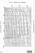
4652/8042 25W, 150 mA, Ug2max=250 V, mu=4, RCA 1969
Unfortunately, data sheet does not have plate curves. Unlike TV tubes, this one is directly heated, a bonus for those who like the sound of filament cathodes. I have a few of these, maybe you can get g1g2 drive curves?
Where is 6KY8 ? I guess about next to 6LU8
In a TV set there are two types of sweep tubes. The name comes from the tubes used to "sweep" the electron beam across the face of the CRT.
The beam is swept horizontally (left to right) by the horizontal output tube (HOT), line output, or line scan tube. There are different names depending on where you live. This tube is also responsible for generating the high voltage (10 to 27 KV) needed by the CRT, and with assistance of the damper tube, damper rectifier, or boost rectifier, generates the boosted B+ used by some circuits in the TV, and by the horizontal output tube itself. In a color TV set some of the convergence signals are also derived from the horizontal output circuit.
The horizontal output tube is operated as a switch in most TV's. The HOT switched a fixed current through the flyback transformer and deflection yoke's inductance causing a magnetic field to build in the deflection yoke, magnetically deflecting the electron beam across the CRT's face. When the beam reaches the other side of the CRT face, the current is switched off, causing the beam to rapidly return (fly back) to it's starting point. The collapsing field creates a huge voltage spike, which is stepped up in the flyback transformer in a manner similar to the ignition coil in a car. The HOT operates as a switch in a TV set, and linear operation was not a major design consideration, but most of them can be operated in a very linear manner.
The "other" sweep tube in a TV set sweeps the beam vertically (top to bottom) and is called the vertical output tube, vertical deflection amplifier, frame output, frame scan, or field scan tube. It also generates convergence signals in a color set.
This tube is often a dual triode, or triode - pentode pair with the smaller half acting as a sawtooth oscillator, and the larger half acting as a very LINEAR AMPLIFIER operating in class A and covering the audio frequency range.
Early TV sets used the venerable 6SN7 for both stages, bigger TV's needed more power, so a few "audio" tubes found their way into the vertical output socket, most notably, the 6V6GT. As TV's got even bigger dedicated vertical output tubes were developed. The 6KY8 and 6LU8 are from this tube family.
I discovered at a young age that the entire vertical section can be lifted from a TV set, the oscillator can be disabled by removing the feedback cap, which is then connected to a guitar cable, connect a speaker to the yoke leads, and poof.....instant guitar amp. Add a 12AX7 for more gain stir well and CRANK it.
The vertical output transformer covers the audio range and drives a speaker quite nicely. The original Bottlehead SEX amplifier exploited this very fact, and consumed the worlds supply of spare vertical output transformers. The new SEX amps use dedicated audio OPT's.
TV sets contain two "sweep tubes" that are very different from each other, but both can be used for audio amps. Most of the dedicated vertical output pentodes have a high G2 voltage rating (300+ volts) which can be abused. Most of the dedicated horizontal output tubes have a low G2 voltage rating (under 300 volts) which doesn't like being violated.
4D32 specs:
50 Watt, 248 mA @ 150Vg2 knee, gm1 = 20,000 @ 300 mA, 9.5 to 10 Mu, 300 mA max DC, Raytheon 1950
4652/8042 specs:
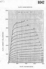
25 Watt, 235 mA @ 150Vg2 knee, gm1 = 6000@100mA (7000 for 8042), Mu 4 (4.5 for 8042), 150mA max DC, RCA 1969 (4652), Amperex 1961 (8042)
6KY8/A specs:
12 Watt, 245 mA @ 150Vg2 knee, gm1 = 8400 @39 mA, 7 Mu, 70 mA max DC, RCA 1963
4D32 looks like it has about 60% the gm2 of similar sized TV sweep tubes (like 6LW6) for the same plate current, due to the high Mu 10 factor, but then the 20,000 gm1 almost fixes that.
4652 has the low Mu 4 going for it, but then a lowish gm1 is not real good, since gm2 = gm1 / Mu
6KY8 looks like a slightly reduced 6LU8
4E27 is a non starter for any g2 drive with 750V max g2 Voltage. It does have a lowish Mu of 5, but gm1 is only 2150 at 50 mA. 150 V on g2 will only get you a 52 mA knee. 200 mA Max DC
some 8042 curves:
50 Watt, 248 mA @ 150Vg2 knee, gm1 = 20,000 @ 300 mA, 9.5 to 10 Mu, 300 mA max DC, Raytheon 1950
4652/8042 specs:
25 Watt, 235 mA @ 150Vg2 knee, gm1 = 6000@100mA (7000 for 8042), Mu 4 (4.5 for 8042), 150mA max DC, RCA 1969 (4652), Amperex 1961 (8042)
6KY8/A specs:
12 Watt, 245 mA @ 150Vg2 knee, gm1 = 8400 @39 mA, 7 Mu, 70 mA max DC, RCA 1963
4D32 looks like it has about 60% the gm2 of similar sized TV sweep tubes (like 6LW6) for the same plate current, due to the high Mu 10 factor, but then the 20,000 gm1 almost fixes that.
4652 has the low Mu 4 going for it, but then a lowish gm1 is not real good, since gm2 = gm1 / Mu
6KY8 looks like a slightly reduced 6LU8
4E27 is a non starter for any g2 drive with 750V max g2 Voltage. It does have a lowish Mu of 5, but gm1 is only 2150 at 50 mA. 150 V on g2 will only get you a 52 mA knee. 200 mA Max DC
some 8042 curves:
Attachments
Last edited:
- Status
- This old topic is closed. If you want to reopen this topic, contact a moderator using the "Report Post" button.
- Home
- Amplifiers
- Tubes / Valves
- More Ruminations on Screen Drive/Crazy Drive