Wanted to go to Diyhink for 15v for the JG buffer...instead I will wait the design of Subbu Design if it s versatile with voltage....Btw my SB Duets are 9 v.
firstly i was trying to feed it with V3 ps...with changing r1 r2...before Gary told me it was not possible without deep hard tweak on it.
firstly i was trying to feed it with V3 ps...with changing r1 r2...before Gary told me it was not possible without deep hard tweak on it.
Btw Gary mistaked first as I did because shceme°20 in the datasheets seemed alowed more than 5 V... I surmise he had to think after to rectify  ... what I am enable to do... after as before ! I would have to learn some theory before and think of it...what I....
This story remenber me a little man whos name was Stradi something... I remenber he maid one or two errors after thinking him devices (IIRC a strings DAC)... and learned from its !
Do you think designing something with straps or pot to change between some std voltages ? (5 V, 9V, 15 V.... -15V) ?
... what I am enable to do... after as before ! I would have to learn some theory before and think of it...what I....This story remenber me a little man whos name was Stradi something... I remenber he maid one or two errors after thinking him devices (IIRC a strings DAC)... and learned from its !
Do you think designing something with straps or pot to change between some std voltages ? (5 V, 9V, 15 V.... -15V
) ?
Last edited:
I had hoped one extra Subbu V3 power supply would have enough current to run a waveIO USB converter. It doesn't.... Can I run my two Subbu V3 power supplies in parallel?
I think each one supplies about 250 ma current....Would two yield 500 ma at the same voltage. That would be enough.
Awaiting the new Subbu PSU of course....
I think each one supplies about 250 ma current....Would two yield 500 ma at the same voltage. That would be enough.
Awaiting the new Subbu PSU of course....
I had hoped one extra Subbu V3 power supply would have enough current to run a waveIO USB converter. It doesn't.... Can I run my two Subbu V3 power supplies in parallel?
I think each one supplies about 250 ma current....Would two yield 500 ma at the same voltage. That would be enough.
Awaiting the new Subbu PSU of course....
If you check the datasheet for the WaveIO USB, it says it needs 5v @ 0.5A. The Subbu DAC needs ~0.1A, so you need at least 5v at 0.6A. I'd suggest a power supply that has some margin, perhaps a 5v supply rated at 1A.
Regarding your question about using 2 Subbu power supplies, even that won't be enough current capability. You could tweak a single PS to supply enough current but you'd need to make some modifications. You'll need a transformer with a larger VA rating, you'll need to heatsink the output transistor to handle the higher current, and you'll need to change the current limit resistor to raise the output current. A careful reading of the LM723 datasheet should show the way.
---Gary
It's been mentioned here and there, but I think it's still an open question. What is the consensus on using the Salas Low Power unit with the V3? Might be overkill, but it does have a good reputation for clean stable power. I bought one for use with a JG Buffer, (GB fell through) but couldn't one also be used with the DAC?
Salas SSLV1.1 Buils Guide
Salas SSLV1.1 Buils Guide
@ Bob
Better go with Reflektor-D if you want to try shunt reg. Its configured for DAC etc. I have a friend's Subbu V3 SE running on Ref-D right now on my main system. Its set for 5V output and 0.4A constant current limit. Both stable and low noise rail on the scope as a combo. Smooth but not veiled big sound and nice dynamics, rich in warmish details. I was wondering if the DAC can "feel" differences in the shunt reg since its just in prereg role and I already measured 7.3 Ohm parasitic resistance on those Pana SMD coils forming the main LC with the polymer caps plus there are local SMD regs. Enough stuff located between the shunt and the digital chips already in other words. I thought lets tweak the shunt reg's open loop gain parameters a bit. And the combination was still calmly responding. If tweaks in same type pass through then there will surely be detectable subjective differences between whole different types of external supplies as well as personal taste and various systems tone related preferences I guess.
Better go with Reflektor-D if you want to try shunt reg. Its configured for DAC etc. I have a friend's Subbu V3 SE running on Ref-D right now on my main system. Its set for 5V output and 0.4A constant current limit. Both stable and low noise rail on the scope as a combo. Smooth but not veiled big sound and nice dynamics, rich in warmish details. I was wondering if the DAC can "feel" differences in the shunt reg since its just in prereg role and I already measured 7.3 Ohm parasitic resistance on those Pana SMD coils forming the main LC with the polymer caps plus there are local SMD regs. Enough stuff located between the shunt and the digital chips already in other words. I thought lets tweak the shunt reg's open loop gain parameters a bit. And the combination was still calmly responding. If tweaks in same type pass through then there will surely be detectable subjective differences between whole different types of external supplies as well as personal taste and various systems tone related preferences I guess.
I already measured 7.3 Ohm parasitic resistance on those Pana SMD coils forming the main LC with the polymer caps plus there are local SMD regs.
DC resistance of the coils is around 8 Ohm, I earlier suggested trying out 47 µH with 5 Ohm DC resistance but did not take the effort myself (having a quantity of the 100 µH ones)
The V3 does not seem to mind.
Last edited:
Yes agree, that's one of the thing which impress me in the V3 !
But I'm not anymore in the Subbu tunning for my hifi system now, nore i'm for the scope measurement competition if ears can't check it !
I'm not going to test 47 uH as nobody seem really care when testing and report ! Maybe before changing of PS on the buffer it seems more logical to first try bigger caps on the buffer pcb to lower the ESR... but this is the "mode" (french word sense) of PS kits nowadays before all the modification which allow good subjective match according your own system ! I always just write just in this philosophy but as anybody care but very fews and staying with "OK" but no to go to "bigger OK about own system"... PS and buffer are more important but come after in a tunning attitude when a Kit is quite "OK" like the Subbu V3 which perform good enough on its ownn !
Well, I'm dull in this summertime, have to make my JG buffer with my two caps missing !
good summer to you and fellows...
DC resistance of the coils is around 8 Ohm
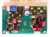
Do L1,L2 SMD coils look like the usual Panasonic 8 Ohm? If yes, maybe there is some tolerance. They were closer to 7 Ohm in this build.
Attachments
Yes, I just measured them and the older ones I have are lower in resistance than the newer ones. The soldering tab is also different. It probably won't hurt to use a coil with lower DC resistance. I doubt if it make a difference except for slightly less voltage loss over the coil.
Last edited:
- Home
- Vendor's Bazaar
- Modifying the Subbu V3 DAC