Now I have som photos and information that might be useful for those who are going to put an solder iron into this box.
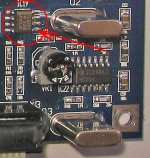
If you are going to keep the original o/p contact, DON'T try to bend the leads going down on the circuit board after cutting. I did that and then it broke deep into the plastic, not possible to solder on. So, better to cut in two places - see red marking. And a Neutrik contact doesn't fit in the original hole...
I slitted the band cable with a razorblade, cutting lead 7,8,10 and 11.
The Zapfilter fits into the box. I haven't found place for power supply board and transformer so they will be placed in a separate box. The 5W on the power board becomes rather hot, so if putting all in the DEQ2496 box - venting holes has to be made (I guess).
So what about the sound?
A way to describe the change in sound is to go from pixeled sound to a more organic flow. The sound became "darker".
Did I loose some energy (and resolution) in the upper register?
I made some adjustments in the mid-high range on the DEQ, going from -2dB to +1,5dB.
Well, no doubt that there is more dynamics, more extension in the lower frequencies.
Around voices a small tendency of "ringing" before now disappeared. I can play at higher sound levels, keeping sonic appearence.
In conclusion, its definintivly worth the hours and money, not saying that Zapfilter is the ultimate solution. There are as Kuei Yang Wang writes others.
An externally hosted image should be here but it was not working when we last tested it.
If you are going to keep the original o/p contact, DON'T try to bend the leads going down on the circuit board after cutting. I did that and then it broke deep into the plastic, not possible to solder on. So, better to cut in two places - see red marking. And a Neutrik contact doesn't fit in the original hole...
An externally hosted image should be here but it was not working when we last tested it.
I slitted the band cable with a razorblade, cutting lead 7,8,10 and 11.
An externally hosted image should be here but it was not working when we last tested it.
The Zapfilter fits into the box. I haven't found place for power supply board and transformer so they will be placed in a separate box. The 5W on the power board becomes rather hot, so if putting all in the DEQ2496 box - venting holes has to be made (I guess).
So what about the sound?
A way to describe the change in sound is to go from pixeled sound to a more organic flow. The sound became "darker".
Did I loose some energy (and resolution) in the upper register?
I made some adjustments in the mid-high range on the DEQ, going from -2dB to +1,5dB.
Well, no doubt that there is more dynamics, more extension in the lower frequencies.
Around voices a small tendency of "ringing" before now disappeared. I can play at higher sound levels, keeping sonic appearence.
In conclusion, its definintivly worth the hours and money, not saying that Zapfilter is the ultimate solution. There are as Kuei Yang Wang writes others.
Hi
Ive just started modding my DEQ 2496. The first thing was to
try to tame the SMPS. I used an active gyrator type filter which
attenuated the line noise somewhat. Next Ive fed the clock inverters with a relatively clean +5V using an LT1763. Also
replaced the ADC & Dac decoupling and voltage reference caps
with Oscons. Also the o/p caps have been replaced. I use the
AES/EBU input from my Pioneer DV565. I can do a direct comparison with my switched pre-amp and the modded DEQ
sounds just a lttle bit veiled compared to the bypass. Next
is to do something about the o/p stage which is currently the
NJM 4580 op amps. Since Behringer wont release a schematic it
looks like Ill have to do my own o/p stage.
Geoff
Konnichiwa,
You can do that. Or if you can read a principle schematic and translate this into what is on a PCB you can mod the original. I can post a principle schematic of the circuit in the DEQ, both analogue input & output, if there interest. Note it will not show component designations but values, which should match the DEQ but may be slightly different.
Sayonara
Geoff4 said:Since Behringer wont release a schematic it
looks like Ill have to do my own o/p stage.
You can do that. Or if you can read a principle schematic and translate this into what is on a PCB you can mod the original. I can post a principle schematic of the circuit in the DEQ, both analogue input & output, if there interest. Note it will not show component designations but values, which should match the DEQ but may be slightly different.
Sayonara
Konnichiwa,
Hmmm, switched mode supplies are a lot better, POTENTIALLY, than their reputation. I'd probably fix the existing SMPS, which is not too difficult if you know what you are doing and have a fast and sensitive 'scope.
DIY Supplies, batteries are always a PITA. I'd probably make a raw 20V + 20V + 9V supply that is choke input and uses multiple layers of RF filtering plus schottky diodes and feed that into the SMPS PCB and upgrade the reg chips there.
If I get the time anytime soon (unlikely) I'll mod my own DEQ.
In mind I have an abridged version of the original analogue stage (I&O) with consumer levels and SE (RCA) jacks (fitted instead of XLR's), the remaining Op-Amp's changed to AD8066 and the "liberated" op-amp's used as DC servos to allow direct-coupling of Inputs and outputs. If I get any suitable size Transformers in time from S&B (it's on their list to develop) I'll use these of course.
Then quiet down the SMPS and upgrade all the digital supplies.
Sayonara
leo van doorn said:What would you suggest as the road to take for the power supply ? Accu/battery based ?
Hmmm, switched mode supplies are a lot better, POTENTIALLY, than their reputation. I'd probably fix the existing SMPS, which is not too difficult if you know what you are doing and have a fast and sensitive 'scope.
DIY Supplies, batteries are always a PITA. I'd probably make a raw 20V + 20V + 9V supply that is choke input and uses multiple layers of RF filtering plus schottky diodes and feed that into the SMPS PCB and upgrade the reg chips there.
If I get the time anytime soon (unlikely) I'll mod my own DEQ.
In mind I have an abridged version of the original analogue stage (I&O) with consumer levels and SE (RCA) jacks (fitted instead of XLR's), the remaining Op-Amp's changed to AD8066 and the "liberated" op-amp's used as DC servos to allow direct-coupling of Inputs and outputs. If I get any suitable size Transformers in time from S&B (it's on their list to develop) I'll use these of course.
Then quiet down the SMPS and upgrade all the digital supplies.
Sayonara
Hi Kuieu
I for one would be interested in any schematics you can come up with. It would take far too much time to reverse engineer the
original design thats why I was thinking of doing my own.
Ive delevoped my own discrete opamp specially for this kind of
application but it is quite big.
I managed to filter the main power rails to the op amps
quite well. I originally tried LR/C networks but this didnt work as well as I hoped due to the inductors interwinding capitance I
think.
I think its worth perserving with this device because even in its current state I like what it does the sound of my system in my room.
Geoff
Konnichiwa,
Analogue Input section:
Analogue Output section:
Sayonara
Geoff4 said:I for one would be interested in any schematics you can come up with.
Analogue Input section:
An externally hosted image should be here but it was not working when we last tested it.
Analogue Output section:
An externally hosted image should be here but it was not working when we last tested it.
Sayonara
DCX2496 minus 16 dual opamps + 8 transformers
hi guys,
I just posted a message in the loudspeaker group about the modification of my DCX2496, hope this link works:
http://www.diyaudio.com/forums/showthread.php?postid=591624#post591624
regards, Peter
hi guys,
I just posted a message in the loudspeaker group about the modification of my DCX2496, hope this link works:
http://www.diyaudio.com/forums/showthread.php?postid=591624#post591624
regards, Peter
Konnichiwa,
Note that I said the anaologue I/O for the DEQ used IN PRINCIPLE the same circuitry. I did a rudimentary trace on my own unit to confirm. I noted that component designations would not line up.
However, for people wanting simple mods it should be non too hard to trace the DAC signals especially to the first summing mp and equally the ADC inputs to the Balancing Dual Op-Amp.
The changing the relevant resistors to the "right" types should be childs play.
Sayonara
stef1777 said:The schematics posted below are for the DCX not the DEQ.
Note that I said the anaologue I/O for the DEQ used IN PRINCIPLE the same circuitry. I did a rudimentary trace on my own unit to confirm. I noted that component designations would not line up.
However, for people wanting simple mods it should be non too hard to trace the DAC signals especially to the first summing mp and equally the ADC inputs to the Balancing Dual Op-Amp.
The changing the relevant resistors to the "right" types should be childs play.
Sayonara
An externally hosted image should be here but it was not working when we last tested it.
A picture says more than...
Hope it helps.
brgs
ryssen said:Is it okay to use LM317 and LM337 to adjust the analog power to +- 12v to use AD8620?For output and input
You can may be use 12V fixed version to have less components to add. Space is counted.
You can may be replace the two caps before reg with better and bigger version, en replace the caps at out with tantalium caps.
I personaly used 2 x 1000UF 35V and 2 x 10UF 25V tantalium.
For the pure passive output stage KYW mentioned, I found this app note in Jensen trans with circuit for CS4396.
http://www.jensen-transformers.com/as/as093.pdf
http://www.jensen-transformers.com/datashts/11ssp8ma.pdf
It uses the very expensive JT-11ssp-8ma "Repeat Coil" trans for voltage out differential dac like the CS4396 which is almost the same as the AKM4393 used in the deq/dcx2496.
Now I don't know is the difference between a split winding "repeat coil" and other 600:600 trans. I have a UTC W-786 600:600 and wonder if this is also suitable for the Jensen output stage. Thanks.
- Home
- Source & Line
- Digital Line Level
- Modify behringer DEQ2496?