Well, that was really my question. It appears to be easier and safer to machine the spindle, rather than the bushings, right? So, why do it the other way round?
They are most likely buying the spindle material spec'd to a common outside diameter, because that's the cheapest way, keeping their turning costs down. We'll assume that this is all done manually. Boring the bushings is actually quite straight forward, if you know what you are doing that is.
")
Oilite can be bored just fine, but you need razor sharp tools and a rigid machine, otherwise the pores get smeared over as mentioned above.
I used to use a Micro-100 solid carbide boring bar for smaller bores. They work really well for CNC too.
jeff
May I suggest Boca Bearing Company :: Ceramic Bearing Specialists
Good lubes and ceramics of most all types. Knowledgeable friendly staff, quick with a reply and reasonable pricing
Mentioning clockworks gumming up is so true, will save mechanisms from further contamination and corrosion.
Ah yah, boca. Remember them from a few years ago. I needed some ceramic bearings with absolutely no metal either for use in a 7 tesla magfield. Coulda used IBEC 9 though, as the app was runout sensitive. I believe we used a tapered Teflon or delrin bushing/spindle combo instead.
As I recall, the ceramic ball surface and sphericity numbers were amazing, but when installed in the race, radial runout was unacceptable.
jn
I made up bearings for car suspension.
Drilled the plastic to size with the closest drill I had available.
Polished the outside of the stainless tube that ran inside that plastic bore.
Turned the OD of the plastic to give a push fit inside the big steel housing. Effectively I had a plastic bush between the steel housing and the stainless rotor.
Tested the rotor in the bush. Slack fit.
Turned another plastic bush with a couple of thou extra on the OD. Still too slack a fit for the rotor.
On my third by this time I had about +4thou on the OD I got a stiff hand push of rotor into bush.
These close fitting bushes kept the dirt out of the modified suspension so well that they ran in competition and driven to and from events for 4years until I sold the car. No sign of wear, despite the mileage. And due to the very good control of the suspension movement they rode the undulations of road driving better than the rubber bushed standard suspension.
I did not use oilite, I can't recall the trade name. But this loading of the plastic bush could easily be applied to a TT rotor/bush.
Are you saying that in order for the plastic (what sort of "plastic" was it??) to run true without off axis "slop" you had to undersize the bore on the plastic, or oversize the OD where it went into a steel housing? This effectively causes the plastic bushing to squeeze out the ends slightly? One could imagine a rubber cylinder being squeezed along the outer surface, causing the ends to bulge (like a blown electrolytic!)?
The TT runs with much lower friction, nil load, and under far less power... so the fit can not be "tight" one might suppose.
The TT runs with much lower friction, nil load, and under far less power... so the fit can not be "tight" one might suppose.
I machine the OD to oversize. That became a vice push/force fit.
This reduced the bore of the platsic bush just sufficiently to become a good hand push fit for the suspension "rotor".
The squeeze required was quite small. I seem to think I used a 1/2" drill for a 1/2" OD rotor. But the straight drilling left a slack fit. Far too slack for a suspension arm and same for a TT rotor. Both need as near zero clearance as possible.
For a plastic with good wear properties and ability to hold tolerances, it was probably some type of acetal.ur not going to share what sort of plastic you were using?
I am curious.
ur not going to share what sort of plastic you were using?
I am curious.
..........I did not use oilite, I can't recall the trade name.............
Please look at the last pic very closely. It looks like there are steel chips embedded in the side wall of the bronze. That can further attack the spindle.
When I re-worked a 3 jaw chuck that was horrible, I locked a piece of brass rod in the tailstock, brought the 3 jaw hardened steel onto the brass, and used valve grinding compound to remove material of the jaws. The compound embeds itself into the softer material, in my case brass, and abrades the harder material, for me the chucks.
The bushing pictured seems to be embedding the steel chips...I would worry about it grinding down the spindle.
I have attached a picture of a steel pivot from a clock, it was running in a BRASS plate. The brass plate had a little wear, but nothing like this.
jn
Speaking of clocks, has anyone considered using a synthetic ruby bearing like they do in high grade clocks and mechanical watches? I wonder how big they make those things... Diameters up to 10mm are apparently available. I also read that some folks use a ruby ball in place of the steel one.
Last edited:
Speaking of clocks, has anyone considered using a synthetic ruby bearing like they do in high grade clocks and mechanical watches? I wonder how big they make those things... Diameters up to 10mm are apparently available. I also read that some folks use a ruby ball in place of the steel one.
My initial thought was that it would be too expensive. Then I realized we're talking audio here...
A hardened steel post finished to 5 millionths of an inch near the bottom where one ruby bearing hits, and a ruby top plate in contact with the rounded post top or ruby ball, with one more ruby washer at top to maintain center.
So two areas maybe half inch long finished on the post, a well for a ball, a small ruby plate for vertical weight, and two ruby washers.
Of course, one could just use three ruby pallets at each bearing surface, those are very cheap.
jn
I think McMaster-Carr sells a variety of suitable thrust bearing surfaces, balls, and materials. Pretty sure they sell a sapphire, ceramic, carbide and steel.
Think it was them, but I know I've seen it in catalogs... was looking for replacement for a SOTA turntable for a friend some years back.
fwiw.
What would "three ruby pallets at each bearing surface" look like??
Think it was them, but I know I've seen it in catalogs... was looking for replacement for a SOTA turntable for a friend some years back.
fwiw.
What would "three ruby pallets at each bearing surface" look like??
What would "three ruby pallets at each bearing surface" look like??
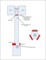
Just run the three pallets as a triangular arrangement, such that the center post contacts all on a line, each contact 120 degrees around the post
At the top of the center post, use a conical cut to center the ruby ball. It can contact another conical cut steel/polished bearing for platter weight, and the cones with ball will center the platter top while supporting weight. Use a wider conical angle on the top so it takes the sliding.
So only one surface of the post needs polishing and hardening, one surface for the platter top bearing.
If runout is difficult to control, use a slight taper at the bottom of the post, and use a threaded insert at top to adjust the table height by moving the upper cone. Turn the insert one way, the platter drops and the lower pallets contact harder. Just make sure that during assembly, the insert is all the way down so the rubies aren't shattered.. In place, check the table for play, adjust the insert accordingly.
jn
A rather broad jump, from oil impregnated sintered bronze to ruby...
I used to manage a bushing manufacturer, we made nickel bronze bushings. IMHO, there is no such thing as a pre sized bushing. The id will always deform when installed. People loved using lower grade materials for bushings because they were so easy for the garage mechanic to size. Just stuff a stepped reamer through it and poof, you can assemble. As a purist I've been trained to view bushings with a critical eye. My experience with turntable bushings is most uniformly dismal. But then I need to remember, 33rpm,no heat, minimal radial force. I can't bag on manufacturers too hard for using sintered bronze, given the requirements but I don't consider it for my builds. There is really only metal to metal contact if there is a lubrication failure, which is why I am gun shy about inverted designs, reservoir on top where the oil is always present on the top of the spindle. The using and spindle are a fluid interface. Just some musings.
I used to manage a bushing manufacturer, we made nickel bronze bushings. IMHO, there is no such thing as a pre sized bushing. The id will always deform when installed. People loved using lower grade materials for bushings because they were so easy for the garage mechanic to size. Just stuff a stepped reamer through it and poof, you can assemble. As a purist I've been trained to view bushings with a critical eye. My experience with turntable bushings is most uniformly dismal. But then I need to remember, 33rpm,no heat, minimal radial force. I can't bag on manufacturers too hard for using sintered bronze, given the requirements but I don't consider it for my builds. There is really only metal to metal contact if there is a lubrication failure, which is why I am gun shy about inverted designs, reservoir on top where the oil is always present on the top of the spindle. The using and spindle are a fluid interface. Just some musings.
A drawing.
ps. You could also just harden the post conical surface, and use a mild steel 14-40 threaded rod with a non hard bottom conical surface. Removes one part in the assembly and makes the platter opening just a simple internal thread. But then, the post conical taper would have to be shallower so the ball slides on the post.
jn
Attachments
Last edited:
jn, you lost me with that drawing!
Why is there a bearing in the form of a sphere on top of the shaft, under the TT platter?
If so, how does the shaft rotate??
I expected to see the taper go the other way, so it sits on three surfaces??
Unless that whole thing is upside down? Yeah, that must be it, you play records upside down!
Why is there a bearing in the form of a sphere on top of the shaft, under the TT platter?
If so, how does the shaft rotate??
I expected to see the taper go the other way, so it sits on three surfaces??
Unless that whole thing is upside down? Yeah, that must be it, you play records upside down!
jn, you lost me with that drawing!
Why is there a bearing in the form of a sphere on top of the shaft, under the TT platter?
If so, how does the shaft rotate??
I expected to see the taper go the other way, so it sits on three surfaces??
Unless that whole thing is upside down? Yeah, that must be it, you play records upside down!
I thought the OP was from Australia.
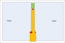
I left the meat of the platter out for clarity of drawing... That went well..
Here's a pic with the full thickness platter.
The green is the 1/4-40 threaded insert with the cone in the bottom. The orange is the hardened post with the tapered surface polished and hardened, and the conical indent in top also hardened and polished. with a shallower taper to make it the sliding surface.
The bottom jewels could be built into a brass insert so the machining in the platter isn't more than a drilled hole. I didn't draw that.
Adjustment is simple. turn the green too far in, the bottom bearings go loose. too far out, the top goes loose. Just right, there is no shake.
jn
Attachments
Last edited:
Ah, I see... the shake or lack thereof would appear to depend on the runout of the center spindle? Of course brass would "work" itself in under the harder ruby...
On top I'd want the adjustment screw to be pushing on a slug that was either flat machined something or other, or have a mating surface to the ball, not direct on a 1/4-40 screw. 40 tpi fine, but not sure I have a die for that?? that 1/4" or 0.250 might be handy because you could slap the center piece for the record down the same rabbit hole?
Provision to lock the adjustment might be good too...
how to hold the three ruby sections in place under the platter?
Interesting approach...
- Status
- This old topic is closed. If you want to reopen this topic, contact a moderator using the "Report Post" button.
- Home
- Source & Line
- Analogue Source
- Modern bearing engineering, a sad story