Consider how much it would have cost using expresspcb's miniboard service: $60 for 3 boards with 6 circuits per board. That's $3.33 per 1"x1" pcb that doesn't have solder mask or silkscreen and isn't v-scored! $2.88 per 1"x1" production quality board is a great deal by comparison.
Edit: If I were to use the Advanced $33 per board deal and panelize 45 1"x1" pcbs on a 6"x10" pcb, that would knock the price down in the $1 per board range but I would still have to cut them out by hand or ask if they could do v-scoring for an extra fee.
Edit: If I were to use the Advanced $33 per board deal and panelize 45 1"x1" pcbs on a 6"x10" pcb, that would knock the price down in the $1 per board range but I would still have to cut them out by hand or ask if they could do v-scoring for an extra fee.
danielwritesbac said:. . . and powerful Nichicon ES too? How unexpected, and, its inspiring as well.
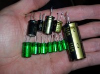
Those are Nichicon Muse caps kindly donated to the cause by motherone along with some LM1875s in exchange for some boards
")
BWRX said:Those are Nichicon Muse caps kindly donated to the cause by motherone along with some LM1875s in exchange for some boards
There's a trick with those. I make a "sharpie" marker stripe on the short-pin side before installation.
Similar Nichicon Muse series caps worthy of interview:
(you already have ES-220)
ES-330
http://www.hndme.com/productcart/pc/viewPrd.asp?idcategory=40&idproduct=1719
ES-470
http://www.hndme.com/productcart/pc/viewPrd.asp?idcategory=40&idproduct=750
KZ-220
http://www.hndme.com/productcart/pc/viewPrd.asp?idcategory=38&idproduct=718
KZ-330
http://www.hndme.com/productcart/pc/viewPrd.asp?idcategory=38&idproduct=766
KZ-470
http://www.hndme.com/productcart/pc/viewPrd.asp?idcategory=38&idproduct=719
Also, Cornell's Mallory SK and Mallory SEK are both good in power circuits. I love their high voltage models, although I've never owned any of the 25v. Cornell publishes spice simulation documents for exact measure. Those caps are at www.alliedelec.com as are plentiful transformers and bridge rectifiers.
Well, I'm off to research some method of making a bass-n-treble control that doesn't involve an RC against the audio path. Tone knobs are usually unnecessary with LM1875, but one of my larger projects really needs some help.
EDIT: and catching up on some long-overdue jammin out
Daniel,
I find it astounding that you are so intimately familiar with these caps without knowing anything about how to order resistors. Do you have any personal experience using ANY of these parts? It looks as if you found Handmade Electronics web site and posted anything relating to Nichicon's "muse" series.
Specifically, you posted a recommendation for two ES series bipolar caps. Typically, when polarity is known, as is the case for these boards, bipolar caps are not appropriate. Do you have a specific reason as to why you are recommending these bipolar caps? I happen to have a fairly decent stash of the ES caps (I used some in my last project, coincidentally) and use them for fairly specific purposes, but NOT for power or decoupling caps!
I agree that the KG caps are good, but I have to ask---do you understand the difference between these and, to take a ubiquitous example, the Panasonic FC series? I simply don't understand your "recommendations!"
dfdye said:Daniel,
I find it astounding that you are so intimately familiar with these caps without knowing anything about how to order resistors. Do you have any personal experience using ANY of these parts? It looks as if you found Handmade Electronics web site and posted anything relating to Nichicon's "muse" series.
Specifically, you posted a recommendation for two ES series bipolar caps. Typically, when polarity is known, as is the case for these boards, bipolar caps are not appropriate. Do you have a specific reason as to why you are recommending these bipolar caps? I happen to have a fairly decent stash of the ES caps (I used some in my last project, coincidentally) and use them for fairly specific purposes, but NOT for power or decoupling caps!
I agree that the KG caps are good, but I have to ask---do you understand the difference between these and, to take a ubiquitous example, the Panasonic FC series? I simply don't understand your "recommendations!"
Resistors:
I have not yet ordered appropriate surface mount resistors because of their typically objectionable pricing schemes and because I have a large box of old-fashioned hole-through mount resistors (that I already own). Buying surface mount seemed pointless until recently.
Selection for specific results:
My recommendation is documented. I talked about making a small collection of suitable contendors (contest of peers), and narrowing it down (via interviewing a selection for seemly results).
Likely capacitance values:
Since Muse ES is shown here: http://www.diyaudio.com/forums/attachment.php?s=&postid=1487511&stamp=1208537188
I provided a link to other likely values of the same capacitor.
For this application, we talked about specifying a value somewhere around 220uF; however, I do believe that 330uF and 470uF are also worth an interview. My apologies that I didn't find 150uF readily available. The links posted above are pages already open for purpose of ordering yet more product from the familar vendor. They also have a fun remote control volume kit that I can't quite remember to buy.
Non-Polar--its okay:
Yes, the ES caps are an unusual choice on first glance. You'll also find Blackgate "N" on some of the AudioSector rectifiers.
Fortunately, polarity on the Nichicon Muse ES (actually an NP) is same as polarized--short pin is negative. Unfortunately, you'll have to mark the stripe yourself, before you trim the pins.
Reasons for Nichicon:
I see that Brian has specified a 25v cap. That worried me. Now I see that he is test driving some Nichicon. I'm no longer worried. In my experience, that brand is very durable and the results seemly. Normally, I wouldn't be brand loyal; however, durability is a prime factor when tolerances are small (or zero margin).
You asked about Panasonic caps:
Personally I'm not able to answer that question because the forum filter would remove the most meaningful parts of the response.
Reasons for my reaction to the photo:
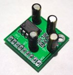
I said that Nichicon Muse was an inspired choice because, although I have used smaller 4.7uF and 10uF ES for rectifier filters (similar to the way that Peter Daniels uses the "N" Blackgates), I had never thought of using them as Brian has pictured above. That appears to be an inspired place for a known high-performance filter capacitor. This was literal. It has inspired me to do exactly as shown in the picture above.
My experience with these caps:
In my own projects, one of the Muse will generally be the winner (as in optimal) about 60% of the time.
That's good.
In addition, I have recently used a little 50v, 22uf Nichicon KZ as an NFB cap referencing onto 120k. It was the runner-up, and although a random very huge Mallory won this time, it took several tries to decide (unusual), so that's still good news for the Nichicon. And, the Nichicon Muse did produce more powerful results along with a seemly frequency response and good clarity--exactly as claimed by the manufacturer.
See photo below.
Attachments
danielwritesbac said:Since Muse ES is shown here: http://www.diyaudio.com/forums/attachment.php?s=&postid=1487511&stamp=1208537188
Just for clarification, those caps in the picture are Nichicon Muse BP.
danielwritesbac said:I see that Brian has specified a 25v cap. That worried me. Now I see that he is test driving some Nichicon. I'm no longer worried.
I said that Nichicon Muse was an inspired choice because, although I have used smaller 4.7uF and 10uF ES for rectifier filters (similar to the way that Peter Daniels uses the "N" Blackgates), I had never thought of using them as Brian has pictured above.
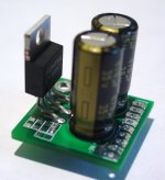
Let me make it clear that I only "dry fitted" those caps on the board because they're the right size, I had them on my desk, and I wanted to see if the footprints for the capacitors was correct! I do not intend to use the Nichicon Muse caps on the supply rails by the chip. I will use 35V rated caps because I plan on using 25V rails. The cap voltage ratings should be determined by what voltages you plan on using, simple as that.
You could use nonpolarized caps on the supply rails, but I don't really see why you'd want to. If you think it will make it sound better then go for it. I plan on using 220uF, 330uF, or 470uF 35V Panasonic FMs on the supply rails.
BWRX said:If you think it will make it sound better then go for it.
Hi Brian! That is something I don't know. Finding out for sure is easily done and I think its worthwhile. Would you like a selection of extras to try out?
Also, a question--does the board contain space for an NFB cap (works without a preamp) or is the dc offset managed by varying the NFB resistors instead, so there's no cap in the NFB (as typically used with a preamp)?
I use the Panasonic FM caps in my LM3875 amps and have no complaints. They're great caps at a good price.
The board doesn't have provisions for a DC blocking cap in the feedback loop, but you could cut the input trace, scrape away some solder mask, and solder a cap in there if you really wanted to. If you need DC blocking you can use an off-board coupling cap on the input.
The board doesn't have provisions for a DC blocking cap in the feedback loop, but you could cut the input trace, scrape away some solder mask, and solder a cap in there if you really wanted to. If you need DC blocking you can use an off-board coupling cap on the input.
BWRX said:The board doesn't have provisions for a DC blocking cap in the feedback loop. . .
Question:
Will you offer a preamplifier to complete it, or will the power amp module be an orphan?
BWRX said:
Thanks!
Oh, that's a good answer. The photo shows the matching preamp.
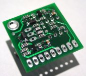
I didn't recognize the schematic on the right side, but if I guessed, by the looks of transistors and voltage divider, I'd think that it lowers and buffers voltage--can power the preamp from the same supply as the amp. Is that right?
You must be a magician to get such a big schematic down to a 1" board.
Or maybe you have one of these?:
Attachments

Yep, that circuit off to the right is one of the simplest ways to make a regulated supply. In this case, it is meant to regulate down the LM1875 supply voltages for the small op amp.
No shrink ray was necessary, just the use of SMDs and plenty of time working in the layout editor
No shrink ray was necessary, just the use of SMDs and plenty of time working in the layout editor
BWRX said:Yep, that circuit off to the right is one of the simplest ways to make a regulated supply. In this case, it is meant to regulate down the LM1875 supply voltages for the small op amp.
No shrink ray was necessary, just the use of SMDs and plenty of time working in the layout editor
Bravo!! That design is so impressive.
Hey Brian,BWRX said:Yep, that circuit off to the right is one of the simplest ways to make a regulated supply. In this case, it is meant to regulate down the LM1875 supply voltages for the small op amp.
This just popped into my head: the regulators will need to handle a pretty substantial voltage drop, no? How well will they be able to dissipate heat in this small package?

I know there won't be much current, so I'm not jumping out of my skin over this, but I have typically seen at least SOME heat sinking for regulators that will be asked to drop a significant voltage. Tell me I'm nuts on this one, and that you have done this before, or are pretty confident the parts will not overheat.
I did do a power dissipation analysis and changed some part values so that everything should be within spec for the parts I want to use.
Here are the changes in reference to this schematic.
D1=D2=18V
R8=R9=100ohm
R10=R11=2kohm
IC1=LM4562
The LM4562 should draw around 10mA quiescent current with ~17V rails and the power dissipation calculations assume that.
Here is the calculated power dissipation for the relevant parts with +/-30V rails for the input to the regulators (max recommended supply voltage for LM1875).
Pd D1=0.092W
Pd R11=0.053W
Pd R9=0.029W
Pd Q1=0.129W
The maximum power dissipation ratings at ambient temperature are 0.1W for the 0805 resistors, 500mW for the SOD123 zeners, and 350mW for the SOT23 transistors. You can see that the calculated dissipation values are comfortably within the ratings of the parts. If you want to use different parts the power dissipation analysis should be done again. If anyone is interested, I made a spreadsheet to automatically calculate this over a range of supply voltages.
Attachments
- Status
- This old topic is closed. If you want to reopen this topic, contact a moderator using the "Report Post" button.
- Home
- Amplifiers
- Chip Amps
- Mini LM1875 design