dfdye said:Daniel,
For resistors, either 1206 (typically 1/4W) or 0805's (typically 1/10W) are readily available from the typical suspects. For caps, the sizes vary greatly, so I would find the part I wanted to use and use the appropriate size. Of all places, Wikipedia seems to have a good chart of common surface mount part sizes, so you might want to glance over that before you start figuring out what parts to use. You can also meander through the Digikey or Mouser catalogs to see what people are selling if you get stuck.
It looks like you are using the ExpressPCB software, which is TERRIBLE!!! I would highly recommend searching for an alternative. Eagle is pretty commonly used by forum members, but I personally like DipTrace since the libraries are much easier to manage IMHO. Each has their own quirks, but each also has a free version, so no loss to install both and see which strikes you. If you have any CAD background, then you should be able to jump into either pretty easily. If not, then the learning curve will be steeper, but each also has a pretty good tutorial and decent help files, so you should be able to get up to speed a little more quickly.
Thanks for the info!! Yes, that's Express PCB software in use. Their software looks like a 1st year collegiate software programming project. I don't have any cad background. But, it wasn't difficult. Better would be nice.
Was the layout okay? Did I get the bridge connections in the right place (for optional bridge mode)?
I could have made about 26 amplifiers on eboard or about half that on vero, in the time spent pushing the computer mouse. Oh well, it was the first time for PCB software.
I also need a vendor that has decent PCB pricings, as the prices that I have found are severely out of proportion.
On the SMT's, it seems that I am asked to buy from $25 to $38 for each value. Its too much. I could buy a mixed bag from Sure, and they'd have it here just in time for Christmas. Is there a faster vendor that provides SMT product for prototyping (a box of variety)?
EDIT: Any recommends for a preamp to add to this?
danielwritesbac said:Was the layout okay?
The basic organization of the parts looked fine to me, but being a perfectionist I would clean up the traces. One thing I don't see is a connection between power ground and signal ground.
danielwritesbac said:I also need a vendor that has decent PCB pricings, as the prices that I have found are severely out of proportion.
We threw out a bunch of names earlier in the thread. Look them up. More often than not you get what you pay for, but some places are pretty good for cheap.
danielwritesbac said:Is there a faster vendor that provides SMT product for prototyping (a box of variety)?
Have you not heard of digikey, mouser, or newark? It's best to buy all your parts at once for a project from them to save on shipping costs.
Looks like a plateful of spaghetti to me, but it appears that all the correct signal paths are present. Why are the small bypass caps so far from the chip? If you're going to design your own board, you might as well include all that we've discussed about various circuit advantages: caps close to chip, short feedback path, etc. Some of your paths are pretty convoluted and not very short. This looks a lot like the QK50 board with a ground path arrangement closer to a star type.
Regarding signal ground to power ground: can this connection be made directly from the input? I mean, does the input signal ground leg need to go through a trace on the board, or can one simply connect that wire to the power ground (star) point? If a design includes a star ground, why not run the shortest path to the star? Why must the input ground go through the PCB at all?
I am still struggling with my own perversion of the QK50 PCB to make it sound decent. I built two amps, and one of them sounds excellent with all the modifications I made to the circuit. The other amp has something wrong with it and I can't figure out what, so I might just start over with that one.
In building these amps, I did run the input signal ground wire from the RCA jack directly to the star ground point instead of soldering it onto the board where the two holes for input wires are. Is there anything wrong with that?
Peace,
Tom E
danielwritesbac said:
Thanks for the info!! Yes, that's Express PCB software in use. Their software looks like a 1st year collegiate software programming project. I don't have any cad background. But, it wasn't difficult. Better would be nice.
Was the layout okay? Did I get the bridge connections in the right place (for optional bridge mode)?
I could have made about 26 amplifiers on eboard or about half that on vero, in the time spent pushing the computer mouse. Oh well, it was the first time for PCB software.
I also need a vendor that has decent PCB pricings, as the prices that I have found are severely out of proportion.
On the SMT's, it seems that I am asked to buy from $25 to $38 for each value. Its too much. I could buy a mixed bag from Sure, and they'd have it here just in time for Christmas. Is there a faster vendor that provides SMT product for prototyping (a box of variety)?
EDIT: Any recommends for a preamp to add to this?
Hi Daniel,
Mouser.com has basically everything available in qty 1. They also have many 'development kits' that are component assortments (But those assortments seem relatively expensive, to me.). They typically ship the same day, if you order early enough (as do digikey.com and alliedelec.com). I recommend registering on their site, so you can save your projects' parts orders, etc. And I VERY strongly recommend also ordering their free huge paper catalog, along with those from alliedelec.com and digikey.com . [Those are virtually the ONLY three vendors that I use, even when building the inventory for my Curve Tracer kits, which have over 1000 parts each.]
You might also want to follow the links (from each part's listing at mouser.com, for example) to the manufacturers' websites, and see if you can order free samples.
The only commercial PCB fab house that I have used is http://www.4pcb.com (i.e. Advanced Circuits). But they are absolutely fabulous! They also seem to be almost painless, for a first-timer.
However... you would need to use a 'real' pcb layout package, which can produce Gerber files (i.e. a software package that is not tied to a specific fab house's proprietary layout format). Make sure you try their (i.e. 4pcb.com's) freeDFM utility. It's wonderful! It also returns a price-quote tool to you, from which your order would also be placed. (For pcb layout, I use Easy PC, from numberone.com, which I truly love. But everyone else seems to use Eagle.)
No pcb fab house that I know of has dirt-cheap prices for small quantities. BUT, for about the same price as five boards, they will make FIFTY (or many more) for you. Most of them also have a 'barebones' type of service, which can be significantly cheaper. Specifying a longer turnaround time can also be significantly cheaper. You can also usually 'panelize' multiple copies of a layout onto one larger board. If you cut them apart yourself, it is usually much cheaper (make sure you add board-edge lines onto the silkscreen layer, if you want to do that).
If you want 'one-offs' or prototypes, or just a few boards, OR if you want them 'in about an hour', it's probably worth making them yourself.
The cheapest and fastest pcb-making method is probably the 'laser printer toner transfer' one that I have posted, here:
http://www.fullnet.com/~tomg/gooteepc.htm
(When I first started, with that method, I actually used MS Paint to do the layouts. However, I recommend using some real pcb layout software, even though anything that can allow you to print black-and-white pcb artwork should work.)
Besides being incredibly fast and very easy, my pcb-making method's main strength is probably that ALL of the materials, supplies, and chemicals, etc (except for PCB blanks), are available 'immediately', in most localities. Mouser.com et al have cheap pre-cut FR4 boards, in both single and double-sided, with various copper and board thicknesses. Ebay.com can also be a very good source for pcb blanks.
The main 'gotcha' of all of the 'homemade' methods is that, for double-sided boards, you wouldn't have plated-through holes, for through-hole components, which can mean that you have to create 'vias' next to pads that will be covered by a component or socket (and will therefore be inaccessible for soldering on the component (i.e. 'top') side), if they have a top-layer track connected to them. Then you have to put a wire through the 'via' and solder both sides.
Have fun!
Daniel,
If you are looking for a resistor kit, Digikey, for example sells several. If you are not familiar with these components, I would highly recommend flipping through their catalog. They have quite a selection, and typically only require a 10 part purchase per value. I have no idea where you are looking that would require you to buy $25 worth of resistors at a minimum!
EDIT: LOL! Here I was getting distracted by the Digikey catalog and Tom posts everything I typed before I hit the "post" button!
I'll add one thing to Tom's post regarding Advanced Circuits ( 4pcb.com) prototype service: If you are a college student and can get mail at a university address, you can order as few as one of their $33 special prototype boards. This is nowhere nearly worth it for small chipamp boards, but for larger projects (up to 60 square inches) this is a heck of a good deal if you can take advantage of it.
Hi Tom! Thanks for the pointers. There's nothing inherently wrong with running a cable right to either side of the loading resistor (that 22k in the pdf), and leaving off the majority of "stuff" shown on my board.
OH!!! Whatever has the strongest ground gets the most power into it. I'd rather that be my speaker than my input source. Does that answer the question?
Shown on mine is a "ground lift resistor" that feeds the input circuit's own star ground. It "may" cancel power thumps and it "may" provide stronger bass. The phenolic prototype does both of those features and its elegant. I haven't tested the homely PCB. Some sort of irony there?. . .
Thanks for noticing the weird extra space. I'll fix it. First time with PCB software for me. Next time, I'll try double-sided and SMT, with preamp, and power supply. That might better-define the application (a monobloc amplifier), so it wouldn't require as much contingencies (that mess on the left side).
Hmm? Preamp. . . Any votes for TDA1524A?
[pp <-- cat typing.
dfdye said:Daniel,
If you are looking for a resistor kit, Digikey, for example sells several. If you are not familiar with these components, I would highly recommend flipping through their catalog. They have quite a selection, and typically only require a 10 part purchase per value. I have no idea where you are looking that would require you to buy $25 worth of resistors at a minimum!
EDIT: LOL! Here I was getting distracted by the Digikey catalog and Tom posts everything I typed before I hit the "post" button!
I'll add one thing to Tom's post regarding Advanced Circuits ( 4pcb.com) prototype service: If you are a college student and can get mail at a university address, you can order as few as one of their $33 special prototype boards. This is nowhere nearly worth it for small chipamp boards, but for larger projects (up to 60 square inches) this is a heck of a good deal if you can take advantage of it.
WOW! Thank you!! You're a mind reader. I was just writing about a larger project. . . Oh, but I'm not a college student. The larger project would have radio and riia. I'm a little stumped on the FM stereo part, although the rest is a piece of cake.
I love the little amplifier, but it would be great to have an entire system in symmetry with it.
danielwritesbac said:Whatever has the strongest ground gets the most power into it.
Here's another case of your terminology leading to confusion. What do you mean by "strongest" ground? The power supply ground traces should ALWAYS present a lower impedance path to ground than an input ground. Ideally the input ground should be at the same potential as the output ground for single ended input and output circuits, which is why you want the input ground and output ground connected BUT you still want to keep the large output ground currents out of the signal ground. You can go the band aid route and do this with a resistor between signal and power ground or you can take care of it with the layout and not need that resistor.
BWRX said:Here's another case of your terminology leading to confusion. What do you mean by "strongest" ground? The power supply ground traces should ALWAYS present a lower impedance path to ground than an input ground. Ideally the input ground should be at the same potential as the output ground for single ended input and output circuits, which is why you want the input ground and output ground connected BUT you still want to keep the large output ground currents out of the signal ground. It's amazing how many people get that confused.
I meant that I would like to avoid having the input ground become the path of least resistance.
The input ground won't become the path of least resistance if you design it properly. You need to see where the large power ground currents will flow, keep their loop areas small, and keep them out of the input ground. Going completely dual mono will cure this and differential inputs also help avoid the ground loop problem so many seem to have. This is the reason I put the differential buffer in front of the power op amp configured as a differential amp. You can reference the differential input signal and the output to ground while avoiding ground loops.
"Strongest Ground" = Alabama clay! Have you ever tried to dig in that stuff?
Back to the discussion at hand, Brian hints at this but doesn't explicitly say that the desire to keep power ground noise out of signal grounds is the driving motivation behind the "star grounding" scheme that is ubiquitous for analog circuit layout. By physically separating the grounding traces/wires, junk can't as easily sneak in the back door via the star ground vs. a scheme in which, for example, the power supply ground was daisy chained through the ground of the signal inputs.
This ties back to Tom E's earlier question: I typically directly connect both my RCA inputs and speaker grounds directly to the star ground, and have personally had good success. If there IS a problem, then the easy thing to do, as Brian said, is to add in a resistor to "bring up" the offending ground. Practically, I just utilized this strategy in my USB amp to separate the potentially noisy USB ground from the "clean" analog ground.
Edit: Or, as the post that I didn't read until now mentions, use a differential input for your opamp and don't worry about the input ground being "off"!
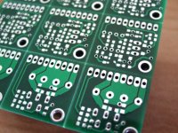
How is the quality of those boards? They look fine, but the solder mask looks strange for some reason. I am quite certain they will be FINE for prototyping, but something seems off from your pictures. The seem reminiscent of the boards I ordered from Olimex a while ago--perfectly acceptable, but definitely not as nice as what I get from Advanced.
Anyway, the layout looks even smaller now that there is a reference point. Quite nice!
Anyway, the layout looks even smaller now that there is a reference point. Quite nice!
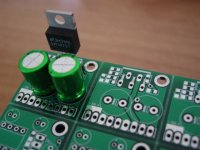
The quality is very good. They don't look any different from boards I've seen that were made by Advanced - nice shiny green solder mask, tin coated pads, and regular white silk screen. The solder mask appears darker in the photos because of the lighting and the camera's white balance setting when I took the photos. I'd have to reinstall Photoshop to do color correction.
This is the first time I had them do v-scoring on the boards and they did a fine job with that too. Just flex the joint back and forth a couple times and the boards break away nicely.
This is the first time I had them do v-scoring on the boards and they did a fine job with that too. Just flex the joint back and forth a couple times and the boards break away nicely.
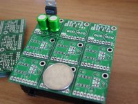
BWRX said:The boards came in the mail today. Time to get my act together and gather/order some parts.
That's a quarter on the PCB just for size reference.
Wow. WOW!!! Those boards are beautiful!
. . . and powerful Nichicon ES too? How unexpected, and, its inspiring as well.
I'm so surprised--very pleasantly surprised. Thank you!!!
- Status
- This old topic is closed. If you want to reopen this topic, contact a moderator using the "Report Post" button.
- Home
- Amplifiers
- Chip Amps
- Mini LM1875 design