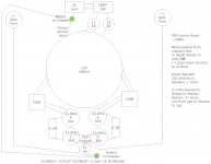
What happens if you have outputs of the two bridges go to the top two capacitors
(instead of directly to the ground point)? Also, what if you take a think wire
connecting the lower CL60 to the top green spot marked bolted to chassis?
Good idea. Picture made clear you wired it differently than I did.
In my Aleph J and H builds I connect bridge rectifiers output (both wires!) to the first cap and made star ground point after the last cap. I assume that your ground point is seeing the high ripple coming of the bridge rectifiers (check PSU designer to see how much this differs). I think it is worth trying!
Hi,
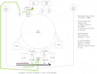
Attached is update of what I think you are telling me to try.
ok, why thin wire between the two bolts to chassis ground?
I measure between the two bolts and get about 0.18ohms,
both ground points should be solid. I thought adding long thin wire
would pick up more noise? Whole chassis bottom serves are chassis ground.
how does removing 1st stage cap grounds from star ground remove
or reduce hum? just curious as I really don't know the difference between
the two.
I also attached the brian gt aleph power supply PCB. Look at the ground,
all caps share same ground plane. I pretty much followed this and other
previous builds.
I wired it back up to the toroid and CRC, input shorted to ground.
I measure same 0.1Vpp at + and - on outputs of last stage caps.
Getting really discouraged. Not sure what else other than build a new
cap bank with the Brian gt board and try again. Only rules out faulty
caps or not.
Thanks
Attachments
Looking back I could have rotated the aleph boards 90 degrees and have shorter
signal wires from RCA jack to aleph boards.
Oh, I also changed to single wires and only have twisted wires for + and - from
cap bank to aleph board now. It's same 0.1Vpp and same hum.
You can try to do everything .. to get ...
put more caps ~100.000UF it will ok ( also separate for each board).
Sorry for the typo: I wrote "think wire" when I meant thick wire to connect
the CL60 to just the single upper chassis ground point (so disconnected from
the lower one).
The simultaneous use of the lower chassis connection can create a ground loop.
Can you easily try this modification first?
the CL60 to just the single upper chassis ground point (so disconnected from
the lower one).
The simultaneous use of the lower chassis connection can create a ground loop.
Can you easily try this modification first?
Last edited:
Sorry for the typo: I wrote "think wire" when I meant thick wire to connect
the CL60 to just the single upper chassis ground point (so disconnected from
the lower one).
The simultaneous use of the lower chassis connection can create a ground loop.
Can you easily try this modification first?
Oh ok I see what you are saying now
I could try that or move AC ground
with long wire to where cl60 ground is
how does removing 1st stage cap grounds from star ground remove
or reduce hum? just curious as I really don't know the difference between
the two.
Attached a pdf on grounding that should make this clear.
Attachments
Attached a pdf on grounding that should make this clear.
Nice article, Thanks.
In the article are only two caps, so regardless of how many CRC stages,
this T is only at the last stage?
since the R ties cap plus and minus, just use wires from 1st cap ground connections to the T?
I will remove 2nd ground point chassis and only use one.
I get it now why the caps are near the rear and trafo is towards front.
I would like to know how AC main wires from AC switch to transformer
placed physically in the amp chassis. it has to cross or be near the cap bank some where before it reaches the the trafo.
Does this wiring diagram look correct now or I'm still not getting it
with the grounding for the caps.
I know I should reverse positions between toroid and caps, hoping to keep
it as and just rewiring.
BTW, the Brian GT Aleph PCB's have a CGND and GND solder pads, so do you
have 2 separate grounds wires going to the PCB or just one ground wire?
Thanks!
with the grounding for the caps.
I know I should reverse positions between toroid and caps, hoping to keep
it as and just rewiring.
BTW, the Brian GT Aleph PCB's have a CGND and GND solder pads, so do you
have 2 separate grounds wires going to the PCB or just one ground wire?
Thanks!
Attachments
I'm looking at picture here:
Aleph through-hole PCB Set | Chipamp Electronics
and I think "OUT" goes to the Speaker+ terminal, "GND" goes to the Speaker-
terminal, which "CGND" goes to the 0V at the power supply.
Aleph through-hole PCB Set | Chipamp Electronics
and I think "OUT" goes to the Speaker+ terminal, "GND" goes to the Speaker-
terminal, which "CGND" goes to the 0V at the power supply.
I'm looking at picture here:
Aleph through-hole PCB Set | Chipamp Electronics
and I think "OUT" goes to the Speaker+ terminal, "GND" goes to the Speaker-
terminal, which "CGND" goes to the 0V at the power supply.
You are correct, the Out goes to Spkr +
On the Aleph board, the CGND and GND are tied together.
That is why I brought it up. The article Albert attached shows Spkr - coming
from PSU. Not which is correct method.
I included your question about your curiosity WHY it is better not to connect the bridge rectifiers to the star point but rather to the first cap in the CRC psu. The paper explains why not all locations on a "logical" star point are equal, even when only one cap is used (as in their example). When more caps are used (CRC, CLC, or CRCRC, etc.) the problem is aggravated.
In general, when someone describes (or models) a circuit there is the assumption that connections have zero resistance (and zero inductance and zero capacitance), but that is an oversimplification. In fact, if you really want to model a circuit ALL resistances, inductances and capacitances of the circuit (in all wires and PCB traces) should be taken into consideration. When we use pre-made PCB's (which is what most of us do) we hope the designer of the PCB took care of this and we just try to keep wires as short a possible and hope for the best. If you were to design you own PCB's however, this would be something to take into account. Just search for "ground planes" in google to see what I mean.
While some prefer speaker and input ground at the star point, there are those that prefer wiring the signal and return wires closely coupled to the PCB (where PCB's support this of course, as the BrianGT boards do). With a well designed PCB this latter option should work fine. The "star point" option however will only work well if it is understood that the "star point" is a simplification and that a small distance can make quite a difference. Why this is so is explained in the article.
Just imagine how much potentials fluctuate in the rectifier output and what this can do to your tiny (in comparison) input signal!
If you decide to use the "star point" option, make sure that you reconfigure you connections (as shown in post #49) so that they are configured like the T in the article. Do not wire everything to a single point.
Something else to consider is that (with 50Hz mains) a 50Hz hum is probably due to the input supply (i.e. comes from the transformer). Only the mains input should have 50Hz frequency.
The rectifier output has double the mains frequency (the negative part of the sign becomes positive) and hence the PSU ripple will have 100Hz frequency.
Ground your input and check the speaker outputs for AC (using a scope or a good DMM in AC setting). What frequency and amplitude do you find? This should point you to where the problem lies.
I hope this helps and good luck. I hope you find the cause.
Sometimes it seems better to avoid "loops", sometimes it seems better to avoid "resistances".
Most times it seems more better to avoid "loops" and "resistances".-?!?!
For years, for decades I think again and again and again to understand - everytime in a new, an other way,-) I am sure, I do misunderstand,-!!!
Most times it seems the best, to avoid the inductivity of trafos and/or to build "better" psus,-)
(Ground) planes I would use to shield - connected with a/the circuit at only one point -, but not to get a defined, clean sounding circuit. In my mind "ground planes" are result of misunderstanding of (the "little one"-) electric circuit. Easy to do, easy to solve problems, but lacks clean, clear "sound".
My mind.-)
I included your question about your curiosity WHY it is better not to connect the bridge rectifiers to the star point but rather to the first cap in the CRC psu. The paper explains why not all locations on a "logical" star point are equal, even when only one cap is used (as in their example). When more caps are used (CRC, CLC, or CRCRC, etc.) the problem is aggravated.
In general, when someone describes (or models) a circuit there is the assumption that connections have zero resistance (and zero inductance and zero capacitance), but that is an oversimplification. In fact, if you really want to model a circuit ALL resistances, inductances and capacitances of the circuit (in all wires and PCB traces) should be taken into consideration. When we use pre-made PCB's (which is what most of us do) we hope the designer of the PCB took care of this and we just try to keep wires as short a possible and hope for the best. If you were to design you own PCB's however, this would be something to take into account. Just search for "ground planes" in google to see what I mean.
While some prefer speaker and input ground at the star point, there are those that prefer wiring the signal and return wires closely coupled to the PCB (where PCB's support this of course, as the BrianGT boards do). With a well designed PCB this latter option should work fine. The "star point" option however will only work well if it is understood that the "star point" is a simplification and that a small distance can make quite a difference. Why this is so is explained in the article.
Just imagine how much potentials fluctuate in the rectifier output and what this can do to your tiny (in comparison) input signal!
If you decide to use the "star point" option, make sure that you reconfigure you connections (as shown in post #49) so that they are configured like the T in the article. Do not wire everything to a single point.
Something else to consider is that (with 50Hz mains) a 50Hz hum is probably due to the input supply (i.e. comes from the transformer). Only the mains input should have 50Hz frequency.
The rectifier output has double the mains frequency (the negative part of the sign becomes positive) and hence the PSU ripple will have 100Hz frequency.
Ground your input and check the speaker outputs for AC (using a scope or a good DMM in AC setting). What frequency and amplitude do you find? This should point you to where the problem lies.
I hope this helps and good luck. I hope you find the cause.
Very good explanation. I used 10 gauge ground wire for multiple caps. One side is connected to bridge, the other side is ground and +-. Zero hum.
Last edited:
Do you can turn the bottom-plate of the chassis? The trafo at the front, thr caps at the back? Some better placed connections/wires would result (ex: not preamp - aleph rca double ground, within aleph 2 times rca ground - two wider apart amps, wider part amps - groundstar).
Your hand-graphed picture: one secondary-winding for + (and - for ground), the other one for - (and + for ground)? Why not both windings for + and -, and central tapping? It would result in a "more honestly" sound too (less differences between + and -).
Do you use to connect amps and psu, and more, "doubled-wire". Not necessary. More diffusity.
To try to get minimal hum, under different circumstances, separate chassis, el. ground, earth (AC-power-in), use wire to connect per luster - to get different combinations to try. May be, you will find different less humming combis, with different sources and so on.
Ok, I pulled most of the wires and rewired what I could.
I did not swap the trafo and caps.
I now have speaker output minus connected directly to aleph boards.
only one one ground wire from aleph board going back to copper plate.
the 2 cap stages are seperated and only joined by wire. only one ground
wire going to chassis ground via cl60.
I am still getting hum with ear next to speakers. The ripple measurements
are different though. at first stage caps, I measure 0.6Vpp and on 2nd
stage caps, I measure 0.1Vpp. On speaker output terminals, I can hardly
measure anything yet I still hear the hum. It is most likely so low my toy
scope is barely picking it up.
how could I tell if it's related to the toroid causing the hum?
do you still think it is incorrect wiring?
I was going to try and add another CR stage in fron of the first stage caps,
but ripple is already at 0.1Vpp, that is low already?
Thanks...
Attachments
")
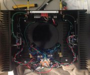
A couple of questions:
Do you have anything connected at the inputs when you hear hum from the speakers?
Does the hum-level change when you only have one input plugged in?
How is the ground wire from the input terminated at the amplifier board?
And unrelated to your hum problem, what's up with the red Wima caps mounted to the back plate of the amp?
Personally, I would rotate the bottom plate 180° so that the power transformer is outside the ground loop formed by input-pcb-capacitors-pcb-input. Look at how the Firstwatt amps ate laid out for example.
A couple of questions:
Do you have anything connected at the inputs when you hear hum from the speakers?
>>>100ohm between sig. input and ground, those yellow rca shorting plugs in the photo
Does the hum-level change when you only have one input plugged in?
>>>no difference
How is the ground wire from the input terminated at the amplifier board?
>>>only one end of the shield braid is tied to rca jack,
other end has only plus and minus directly to pads.
input minus is shorted to GND, SE
And unrelated to your hum problem, what's up with the red Wima caps mounted to the back plate of the amp?
>>>one on each of the DPDT switch terminals to prevent spark, I have seen the switch actually
glow a few times when switching on
Personally, I would rotate the bottom plate 180° so that the power transformer is outside the ground loop formed by input-pcb-capacitors-pcb-input. Look at how the Firstwatt amps ate laid out for example
>>>yes, I know few have mentioned to rotate 180. everything is pointing to toroid. it is not easy rotate 180, might not have enough room do to postion of switch hitting caps.
this is for a friend, he has 94dB sens. spkrs, why I'm trying to reduce hum,
personally not an issue for me with hum, ears being next to speakers.
- Status
- This old topic is closed. If you want to reopen this topic, contact a moderator using the "Report Post" button.
- Home
- Amplifiers
- Pass Labs
- mini Aleph hum