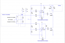
My latest effort regarding a prot circuit that only opens dcb1 output after both shunts show more than 8 volts.
It uses comparators with histeresis (because salas shunts take time to settle)..
Not sure what value should I use for input (R14 to R17)... I want min inpact on the shunts so the protection circuit does not leave a perceptible sonic signature.
It uses comparators with histeresis (because salas shunts take time to settle)..
Not sure what value should I use for input (R14 to R17)... I want min inpact on the shunts so the protection circuit does not leave a perceptible sonic signature.
Attachments
Not the DCB1 integrated shunts we should clarify. Those settle fast, are fixed voltage, straightforward, also having a very reliable record. You are referring to V1.2R with regulated output fed BJT cascode CCS "tail" and "kick starter" Zener. There is the JFET cascode tail example too that needs no kick starter because it auto biases. Its a tweaky non fixed voltage regulator I designed in 2010 and can be found in the simplistic regulators general thread. Links are available a few posts back from here.
Mesmerize 2SK170 BL and resistor questions
Hello everyone. This is my first post so please bear with me. I am new to DIY; I built the ACA first and then Tavish designs Classic tube phono preamp. So now I have embarked on building the DCB1 with the Mezmerize board. I try to find answers to most of my questions by searching this site but I've run into an issue with some SK170bl's I bought recently from a source cited as reliable in this thread. I'm using Salas's Idss measuring method, thank you btw Salas. G & S shorted connected to -, drain to 10R resistor then to + using 9V battery. Using I=V/R I haven't gotten anything lower than 14.9 mA. So, either I am measuring wrong or these are fakes. The vendor has offered to take them back and refund my money but I just wanted to check with you guys first. Maybe I am not testing them right. However last night I saw another post by Salas saying real ones should have a 1 like an "l" and the 7's tail should be slightly curved. Mine aren't like that. If you guys agree they are fake do you know of any reliable sources?
I also was wondering what vendors you used for the audio grade resistors on the BOM. I inquired about Takmans and an Alps r47 20 ohm at Parts Connexion and they quoted $27 for parts and $26 for FedEx ground shipping, $14 with ups and then untrackable mail for $7.95. I know it's not that much but it all adds up. Thanks for all the great advice you guys have posted on this site.
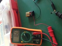
What model meter you use? There is a chance the DMM gives rough mV readings on the 10R voltage drop that can easily mislead the mA calculations by much because its a very small drop. Put the meter selector to series mA mode and the black probe in the mA socket to measure current flow between B+ and drain without any resistor so to confirm the initial indications. Watch it with the probes not to short the battery through the meter though because its internal mA socket fuse will blow.
Tell us the results and attach a close up picture of those JFETs also. Then we will be able help you reach a safer conclusion.
See about prices and shipping for Dale RN60/CMF60 50ppm instead from major vendors. Very good alternatives.
Thank you Salas. My meter is an Extech MN35. I measured four of them for current without the 10R as you suggested and got 12.8 to 15.7mA. Three of the four were over 15. To double check I measured V again with the 10R. I'm attaching a pic with results. Also attaching my test setup just to make sure I had it right. Also a close-up of one them.
Thanks for the resistor info too.
Thanks for the resistor info too.
Attachments
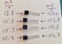
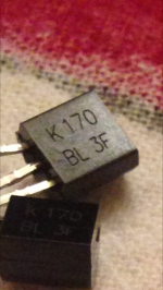
Surely not the right JFET product. The budget Extech meter proved consistent. The series connection mA test looks properly wired also. Alweit from Israel sells matched quads on ebay at about $15 with the postage. People say they are OK. I don't know if Tea could also help you with any spares outside his mini kits or if Andrew still has proper Idss LSK170 matches for dcb1 use to offer. Spencer of www.fetaudio.com used to be a good source also.
I still have lots of grade A and grade C in matched pairs.
But I'll repeat yet again, only one pair in each channel in a DCB1 needs to be a selected Idss type. It does not need a matched pair.
Salas's new pre-amp will need matched pairs and my grade A will be perfect for that. Don't waste matched pairs in a DCB1.
But I'll repeat yet again, only one pair in each channel in a DCB1 needs to be a selected Idss type. It does not need a matched pair.
Salas's new pre-amp will need matched pairs and my grade A will be perfect for that. Don't waste matched pairs in a DCB1.
Hi again. I've got almost all my parts(170s on the way from Spencer(thanks Salas). Just two questions:
1) Can I replace BC517G with BC517_D74Z? Data looks the same except for 1.2A max cc current. I saw the #1047 post about BC550 with 100nf cap. I have those too. I'd just prefer one part.
2) With BOM Mouser yellow LEDs I can match V exactly for both runs but can't get less than 5.7V and 9.5V. That ok or should I get some reds to bring those closer to 9V and 5.4V?
Thanks,
Dan
I trying not to ask too many questions and get as much info as I can by searching but I would feel better if you guys could have a look at my test numbers so far:
- Board test points: +10.6Vdc & -10.04Vdc
- Vdrop across 68Rs: +2.11V & -2.01V
- Offset right: -1.7
- Offset left: +0.03
Do these look OK? I'm a little bummed since I really tried to get the LED strings matched; the yellows were a little high so I mixed in some reds. I'm not sure why the offsets aren't better. My matched quad jfets were supposed to have an Idea of 7.85mA. Unfortunately, assuming they were closely matched, I didn't measure them before soldering. Also I read in this thread that the offsets should be slightly negative. My left one starts at zero and then moves up to +0.03. The right one starts at about -1 and then goes up to about -1.7.
Thanks
-1.7Vdc or -1.7mVdc?
are you measuring +0.03Vdc or +0.03mVdc?
if you have two identical jFETs and use one as the lower CCS with Gate connected to Source then Vgs=0 and Id = Idss
That Id will pass through the upper jFET and since it's Id = Idss then it's Vgs must be zero, if both jFETs operate at the same temperature, i.e. Tj=25°C.
If you have a slightly lower Idss jFET and fit that in the lower position then it's Id is less than the Idss of the upper jFET. That means the upper jFET has a Vgs that is slightly negative.
If you swap these two slightly disimilar jFETs, the lower CCS jFET pulls a bit more current than the upper jFET Idss. This forces the upper jFET to a slightly positive Vgs.
A tiny transient +ve Vgs does no harm.
A tiny continuous +ve Vgs does no harm if the Vds and the Tj are both low.
But if you have a hot jFET and/or a high Vds and have a high transient +ve Vgs you are into the region of excessive gate leakage. That is not a good area in which to operate an audio signal handling jFET.
It's a lot of conditions to hit this poor operating area.
The easiest way to avoid, is to ensure the continuous Vgs is not +ve and that the Tj is kept low.
Last edited:
Thanks Andrew. The offsets are in "mVdc". So the positive one is just slightly positive. In fact it started at zero and very slowly moved up to +0.03mV after 10 minutes or so. I guess I'm just wondering if that 0.03mVdc positive offset warrants swapping the jFETs.Thanks again.
0.03mVdc is so small I cannot measure that. And because it is so low there is no chance of hitting excessive leakage with a Vds of ~10Vds
But if I could, I would swap them just to see that it really did become -0.03mVdc.
What prevents that -1.7mVdc getting amplified before you hit your speaker with it?
But if I could, I would swap them just to see that it really did become -0.03mVdc.
What prevents that -1.7mVdc getting amplified before you hit your speaker with it?
- Home
- Amplifiers
- Pass Labs
- Mezmerize DCB1 Building Thread