
Yes this was common knowledge for many many years. however I have seen quite a few LEDs with the anode being the largest contact....Too bad as it seemed a kind of standard in a world with many standards
")
I have one batch of LEDs that has the big reflector bowl on the other side. Prior to receiving these oddballs, I had thought that the big reflector bowl could ONLY be on the negative side. But there are exceptions waiting to trick us!
Yes, I can confirm that the BIG side is not a universal guide.Yes this was common knowledge for many many years. however I have seen quite a few LEDs with the anode being the largest contact....Too bad as it seemed a kind of standard in a world with many standards
Shame, since 3mm LEDs are not big enough to include the flange with the flat.
We have to rely on the long +ve lead and test each one as the final check.
Results 1 and 2OK, I checked some voltages and something isn’t right.
AC:
+14.08V
-14.08V
Mid board test points
+9.66V
-9.65V
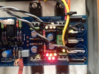
Triplex LED’s
+5.54V
-5.72V
Quintet LED’s
+9.15V
-9.30V
DC Offset
Don’t seem to be getting anything.
Voltage across the output diode is a couple of millivolts.
It seems at one point I measured 17+ V on the output leg of the regulator but now see 10.6V.
Could I have toasted it with an ill-fitting sink, since removed?
AC cannot be +ve and -ve !
Millivolts DC need to be measured on a voltmeter that can resolve small milli-volt measurements. Try using a 199.9mVdc range. If you don't have that then buy a meter that has both 199.9mVdc AND 199.9mVac. In the meantime you will have to made do with using 1.999Vdc to measure the low milli-volts offset.
The output offset of the DCB1 should never be +ve. It should be 0.0mVdc, or very slightly -ve, i.e. less than -1.0mVdc
~-0.2mVdc is often reported by Builders.
Last edited:
OK, I checked some voltages and something isn’t right.
AC:
+14.08V
-14.08V
Mid board test points
+9.66V
-9.65V
Triplex LED’s
+5.54V
-5.72V
Quintet LED’s
+9.15V
-9.30V
DC Offset
Don’t seem to be getting anything.
Voltage across the output diode is a couple of millivolts.
It seems at one point I measured 17+ V on the output leg of the regulator but now see 10.6V.
Could I have toasted it with an ill-fitting sink, since removed?
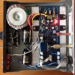
Where are the 4700uf electrolytics gone? You need them.
Results 1 and 2
AC cannot be +ve and -ve !
Millivolts DC need to be measured on a voltmeter that can resolve small milli-volt measurements. Try using a 199.9mVdc range. If you don't have that then buy a meter that has both 199.9mVdc AND 199.9mVac. In the meantime you will have to made do with using 1.999Vdc to measure the low milli-volts offset.
The output offset of the DCB1 should never be +ve. It should be 0.0mVdc, or very slightly -ve, i.e. less than -1.0mVdc
~-0.2mVdc is often reported by Builders.
If that's the case my offset readings seem high. Using a better DMM I'm seeing -3.00mV on one channel ((L) and -1.5mV on the other. The Jfets are said to be matched.
Also +9.3V and -9.42V on the 5 group LED's, +5.54V and -5.71V on the 3 group LED's, +9.88V and -10.05V on the rails.
Can I do better on DC offsets?
Also, are 6800uf/63V capacitors suitable alternatives to the 4700uf specified?
TIA
Keith
Attachments
I had set a +/-5mV max offset spec so you are still in. Especially if your power amp is low voltage gain and/or AC input coupled i.e. having an input series capacitor
6800uF 63V is OK but try mount them with rigid copper extensions much nearer to the original 4700uF pads. If you might got another use for them look for suitable size and pitch 4700uF 35V Nichicon
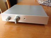
The little box's face looks nice BTW
6800uF 63V is OK but try mount them with rigid copper extensions much nearer to the original 4700uF pads. If you might got another use for them look for suitable size and pitch 4700uF 35V Nichicon
The little box's face looks nice BTW
I had set a +/-5mV max offset spec so you are still in. Especially if your power amp is low voltage gain and/or AC input coupled i.e. having an input series capacitor
6800uF 63V is OK but try mount them with rigid copper extensions much nearer to the original 4700uF pads. If you might got another use for them look for suitable size and pitch 4700uF 35V Nichicon
The little box's face looks nice BTW
Hi Salas,
I think I'll swap the caps for something that fits, like the Nichicons. The power amp is a Dynaco 70 clone so I'm guessing I'll be OK. I'll let you know how it sounds when I get there.
Thanks again,
Keith
I put more effort into matching LED's and Jfets, installed 4700uf caps directly to their pads, and gave it a listen tonight. Huge improvement over the vintage Sansui pre that preceded it. Thanks Salas and others for helping me sort this out; it has been a worthwhile endeavor.
DCV= 18.3 both sides, test pads = +9.92V, -9.82V, triplets= +5.55, -5.53V, quints = +9.29, -9.17, across 10 ohm resistors = + 1.69, -1.56, offsets = -.38mV and -.31mV
DCV= 18.3 both sides, test pads = +9.92V, -9.82V, triplets= +5.55, -5.53V, quints = +9.29, -9.17, across 10 ohm resistors = + 1.69, -1.56, offsets = -.38mV and -.31mV
Last edited:
Hi Salas,
I think I'll swap the caps for something that fits, like the Nichicons. The power amp is a Dynaco 70 clone so I'm guessing I'll be OK. I'll let you know how it sounds when I get there.
Thanks again,
Keith
check your output offsets again. They should be slightly negative.
Hi Andrew
Yes they are negative..you posted before I added minus signs in an edit to my 12:05 post.
Keith
Congrats KeithI put more effort into matching LED's and Jfets, installed 4700uf caps directly to their pads, and gave it a listen tonight. Huge improvement over the vintage Sansui pre that preceded it. Thanks Salas and others for helping me sort this out; it has been a worthwhile endeavor.
DCV= 18.3 both sides, test pads = +9.92V, -9.82V, triplets= +5.55, -5.53V, quints = +9.29, -9.17, across 10 ohm resistors = + 1.69, -1.56, offsets = -.38mV and -.31mV
615498,
don't drop the leading zero for values less than 1
Some fonts and some backgrounds make the "." very difficult to see and the number gets misread.
0.38mVdc is less ambiguous than .38mV in some situations and can't be mistaken for 38mV
This makes sense...will remember.
Hi Salas
I built a new power amp that does not have any dc protection circuit and want to use it with the DCB1.
According to my simulations, if the positive shunt does not work and the negative one is ok, I get around 250mV offset out of the DCB1. (Remenber my DCB1 uses V12R that sometimes refuse to start)
As my new power amp has 10x gain I will get 2.5VDC out to the speakers..... not drastic but not totally safe so I decided to include a safety circuit in the DCB1.
The idea is to shunt the DCB1 output to GND in case of psu fault.
Please have a look at my first draft and let me know if it is feasible.
I built a new power amp that does not have any dc protection circuit and want to use it with the DCB1.
According to my simulations, if the positive shunt does not work and the negative one is ok, I get around 250mV offset out of the DCB1. (Remenber my DCB1 uses V12R that sometimes refuse to start
)As my new power amp has 10x gain I will get 2.5VDC out to the speakers..... not drastic but not totally safe so I decided to include a safety circuit in the DCB1.
The idea is to shunt the DCB1 output to GND in case of psu fault.
Please have a look at my first draft and let me know if it is feasible.
Attachments
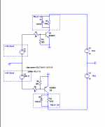
Note: As in my DCB1 I am using two V12R shunts positive connected in tandem I do not have a center tap TX.
Both V12R are powered by a singular isolated secondary.
I do not have a negative raw supply so I would like to improve my design so I can fire the two relays using only one positive 7812...... How can I do that ?
Both V12R are powered by a singular isolated secondary.
I do not have a negative raw supply so I would like to improve my design so I can fire the two relays using only one positive 7812...... How can I do that ?
Hi Salas
I built a new power amp that does not have any dc protection circuit and want to use it with the DCB1.
According to my simulations, if the positive shunt does not work and the negative one is ok, I get around 250mV offset out of the DCB1. (Remenber my DCB1 uses V12R that sometimes refuse to start
As my new power amp has 10x gain I will get 2.5VDC out to the speakers..... not drastic but not totally safe so I decided to include a safety circuit in the DCB1.
The idea is to shunt the DCB1 output to GND in case of psu fault.
Please have a look at my first draft and let me know if it is feasible.
Likely your power amp won't have 0 dB bandwidth @ DC, so it would be lower than the value you estimated
Shuting outputs to Gnd is fine I guess, it will make your inputs silent on power amp
Regards,
nAr
Hi Salas
I built a new power amp that does not have any dc protection circuit and want to use it with the DCB1.
According to my simulations, if the positive shunt does not work and the negative one is ok, I get around 250mV offset out of the DCB1. (Remenber my DCB1 uses V12R that sometimes refuse to start
As my new power amp has 10x gain I will get 2.5VDC out to the speakers..... not drastic but not totally safe so I decided to include a safety circuit in the DCB1.
The idea is to shunt the DCB1 output to GND in case of psu fault.
Please have a look at my first draft and let me know if it is feasible.
Ricardo hi
Firstly at such voltage level you can use the jfet cascode ccs tail v1.2r version that does not feed from the output so not to risk non start (although and the bjt cascode one can be secured starting with a zener, it was mainly added as a version to can go high rail). Here is a jfet cascode v1.2r build with BF256 Q3 and all others K117 http://www.diyaudio.com/forums/power-supplies/192625-sslv1-1-builds-fairy-tales-365.html#post4771610
Dcb1 already shunts to ground during relay delay so doing that won't destroy it with both rails on but check its jfet dissipation won't exceed limits when output is to ground and one rail is down.
Thank you for the input Salas
Allready simulated the worst case with plus rail down and the lower jfet dissipates 80mW....while outputting 250mV... seems ok.
I wired the protection bjts so they will open the relays when shunts are producing around 8vdc each....
Now I would like to use only a positive +12vdc supply to control both relays..... is it possible ?
The designation number Q3 refers to the 1.2R schematics link on the general regulators thread. The first ones on the left. http://www.diyaudio.com/forums/powe...-voltage-shunt-regulator-320.html#post2361983
Originally Q3 2N5459 Q8 2N5457 Q4 Q9 K170. But the recent builder could not easily find so I suggested to sub with Q3 BF256 and all other K117. It worked and he liked it. I have linked it, but if it does not get you there its was in posts #363-#3650 on "SSLV1.1 builds & fairy tales" thread.
About the control circuit for 8V rail relay cut off I guess its workable but you better breadboard it first.
- Home
- Amplifiers
- Pass Labs
- Mezmerize DCB1 Building Thread