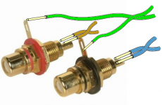
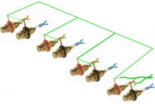
Every connection from a Source to a Receiver is a two wire close coupled pair.
I see 4 bundles of spaghetti with nearly a dozen wires in each. What are you doing?
They are from cat6 cables. A pair for each for R and L and pair for Gnd.
Attachments
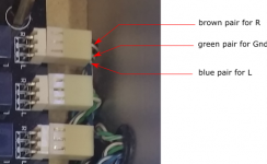
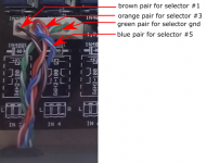
why a pair for Gnd?They are from cat6 cables. A pair for each for R and L and pair for Gnd.
The Source has a flow and return. That is your pair.
each source has a separate flow and return. You do not separate out all the returns and change them to GND.
You probably have a ground problem. You also have far too much wire. Can you hear the relays clicking when you turn your selector switch or when you power up?
Woven or plaited wires will not improve sound quality, just the opposite.
As Andrew points out you should have just a single pair of twisted ground and signal wires for each signal path.
Woven or plaited wires will not improve sound quality, just the opposite.
As Andrew points out you should have just a single pair of twisted ground and signal wires for each signal path.
It buzz when connect to an amp even without switching on the DCB1.
I am only using 3 inputs.
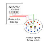
You have populated relays for inputs 1,3,5 not 1,2,3 so check that your selector closes the proper connector socket ends to ground for its own positions 1,2,3 with the DMM's continuity mode at pcb pads level to make sure the connections work, also listen for clicks.
why a pair for Gnd?
The Source has a flow and return. That is your pair.
each source has a separate flow and return. You do not separate out all the returns and change them to GND.
It was done this way in the image. But since all the gnd is connect at the board, should i just use one gnd wire to connect all the rest?
Attachments
You have populated relays for inputs 1,3,5 not 1,2,3 so check that your selector closes the proper connector socket ends to ground for its own positions 1,2,3 with the DMM's continuity mode at pcb pads level to make sure the connections work, also listen for clicks.
Yes, I can hear the clicks of all the relays. it clicks when power up and clicks when shut down. It clicks when the rotary switch is turned (only 3 turns and the 4th to 6 clicks produced no sound).
But the click at the powering on is very quick.....almost instantly upon powering up. Does that matters?
Last edited:
For buzz the quick on is not related. How many volts DC spec are the relays? Is the board an old single layer original?
Those are 5v relays but I have the two 600 ohm resistors in placed. Yes, it is the old original single layered board.
If your relays are 12V replace one of the two resistors below the C517 with a jumper. Check that your volume pot is not connected wrong and that its metal body parts have continuity to ground also. Check continuity of each selected input to pot. Check continuity of all inputs/outputs ground side to center tap Tx connector input middle screw.
Check that your volume pot is not connected wrong and that its metal body parts have continuity to ground also.
The metal body part of the pot have to be grounded as well?
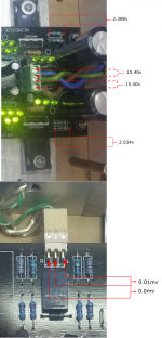
the diodes across is 20.66v - 20.73v. Thats the diodes at the transformer.
For the input diode at each selector turn :
1st diode at first turn = 6.68v
2nd diode at 2nd turn = 6.70v
3rd diode at 3rd turn = 6.77v
for the output diode :
1st diode at first turn = 0v
2nd diode at 2nd turn = 0v
3rd diode at 3rd turn = 0v
but when nothing is selected the diode at the output measured st 2.97v.
Last edited:
The metal body part of the pot have to be grounded as well?
Yes either through chassis metal panel that already has connection to the PCB's ground or with a wire from the pots body to the PCB ground.
- Home
- Amplifiers
- Pass Labs
- Mezmerize DCB1 Building Thread