You can swap tubes as a simple check, but I suspect this is not a tube issue.
Since the unit was damaged in shipping, I'd use a very bright light and a magnifying glass to closely inspect the PWB, it's component solder joints, traces for fractures, etc as well as inspecting all tube socket and chassis mounted disctete component solder joints.
Thermal expansion could cause a fracture to open up as the amp warms up.
I think you nailed it, Ian!
I'm almost certain now the problem was the SOURCE!
I've been using my 80's era Harman/Kardon HD400 CD Player for a long time with no problem, but looks like it was what was causing the (above posts) with my new Meng.
It was hard to imagine that the Harman/Kardon would pick exactly the time of my Meng's maiden voyage to decide to go bad!
Anyhow: hooked up my (also '80's era) Onkyo CD player (DX-702), and the Meng now sounds great!!
So thanks again, Ian.
(and: I guess, regarding the Harman/Kardon, that its power supply is implicated?)
If both channels are dropping in and out at exactly the same time, it is likely to be a power supply problem, or even a source problem (as in CD player - but that is a long shot).
Ian
I'm almost certain now the problem was the SOURCE!
I've been using my 80's era Harman/Kardon HD400 CD Player for a long time with no problem, but looks like it was what was causing the (above posts) with my new Meng.
It was hard to imagine that the Harman/Kardon would pick exactly the time of my Meng's maiden voyage to decide to go bad!
Anyhow: hooked up my (also '80's era) Onkyo CD player (DX-702), and the Meng now sounds great!!
So thanks again, Ian.
(and: I guess, regarding the Harman/Kardon, that its power supply is implicated?)
Starne, glad you found the problem.
Just a final update on the Meng that lives here - I recently "converted" my (modified) Meng Yue to 240V operation, instead of running it from 220V through a line conditioner/stepdown transformer unit. The local mains here is usually 248V. There were a few schematic changes to allow this, mainly providing a greater negative bias voltage for the output tubes which now have around 280V across them, cathode current is set to 31mA. Heater voltages are 6.5V. Bias voltages are around -20V on the output tubes. I think it may sound better with the extra B+, or, I can safely say that no sound quality has been lost, even with the lesser B+ on the small signal tubes. The amp is now doing duty driving some 4 inch full-range boxes on my wife's PC. She is very happy with this situation. Development will go no further, unless I need something to test some hare-brained scheme on.
In hindsight, I think I worried about breaking the max stated limits of plate voltage a lot more than I needed to, time will tell. The OPT's must be good enough or it wouldn't sound as good as it does. If anyone wants a tube amp to experiment and learn with, at around $200 delivered this is good value IMO. It sounds pretty average stock, but still pleasing to someone who has not owned a tube amp before, and better sound IMO than any SS amp I have owned, but thats just MO. The circuit can be improved a lot and a surprisingly nice result is possible. I have really enjoyed learning about tube circuits and power supplies with this amp, all good clean fun. Note that in the pic my Meng Yue has the wider chassis but the narrow chassis one is identical internally and cheaper, except that it has 520 ohm cathode resistors on the output tubes instead of 360 ohms that came with mine, so it has a very good chance of surviving on 245V mains straight out of the box.
The best lessons I learned with this amp, is that I ended up tweaking the amp to suit my ears and my wife's ears, and found that what "should be correct" didn't always sound the best to us, sometimes yes and sometimes no. Also that what's happening on the screens of the output tubes has a huge very big influence on the sound in pentode mode, just changing the screen grid resistor value, or having a regulated screen voltage, all have a big influence on sound quality/character. Also that every tweak I do could be covering up for some deficiency somewhere else in the amp (coupling caps, resistors, OPT's, power supply quality), or in my speakers, or in the acoustics of the room even...
Something else, if you want really good sound quality, it is unlikely that you will get it any cheaper by starting with an amp like this compared to building a Baby Huey/Red Light District/El Cheapo or some other amp, in fact you may never achieve that quality. What you can do with this amp is learn about tube circuits, and that is invaluable if you are into tinkering. I've got bags of now-used parts that have been through this amp, at least $200 worth. I found that by tweaking/modifying this amp, it gave me enough confidence to build another amp from scratch, and modify it just as I did the Mengyue.
I still think the LTP topology with CCS in the tail is definitely worth a try as in El Cheapo or Baby Huey, but I will try that in some other amp in due course. Last schematic.
Ian.
Hi everybody
I´m new to tube amps. I am considering buying the MA 6P1 Mini. But will it drive my Jamo 507 speakers? They are 4 ohms and 150 watts. I also have a Luxman l-430 amplifier witch I will use as a pre-amp. Will this give me any better sound or is the Luxman better than a MA 6P1?
If not, what cheap chinese tube amp will you recomend.
Thanks in advance
Kriss
The only specs I could find on the Jamo 507 were in a review, and stated that the manufacturer specs claimed 88db/W-M efficency, but their measurements indicated it was more like 84dB/W-M.
Article | Jamo 507 loudspeaker | Page128 - August1994 - Gramophone Archive
If that is true that the actual efficency is in the low 80s, then the low efficiency will require more power than the MA 6P1 Mini can deliver to produce reasonable sound levels in most room settings.
I would think the EL34 amp would be more suiting for such speakers.
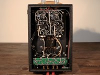
Just bought a Meng Yue Mini X3 EL34 amp if anyone want to see inside ? Still badgering the seller for a schematic though 
Sounds pretty sweet out the box, bass is limited but that's to be expected driving AR's !
Sounds pretty sweet out the box, bass is limited but that's to be expected driving AR's !
Attachments
A schematic would be good, but it would be fairly easy to trace the circuit.
Do you have any method of measuring the power output? EL34 in SE should be about 6W, far from the 24W claimed in the adverts.
I'm still a beginner so little sounds easy to me
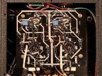
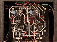
I took a peekaboo inside (Yes I am fully aware of the dangers etc...) And none of the component values match the silkscreen, is this cause for concern ? I have marked on the pictures below...
Also the earth & negative wires on the AC inlet are not connected
In your opinion where's the best place to connect the earth to ? I wont be using the amp until I have connected it.Thanks for the help + if you want any info on the internals / anything I can measure just let me know.
Attachments
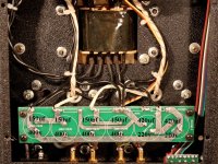
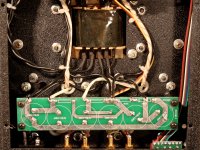
I wouldn't worry about those component values. The Chinese seem to use whatever comes to hand, and judging by the wire straps on that PCB in the last pic (high voltage power supply), the PCB isn't being used in the way the silk screen may have been designed for.
There will likely be an unused terminal on the ac inlet socket. If you look at the socket from the outside, it should be the centre (and offset) pin that needs to be earthed, not either of the other two terminals. You also need to check that the power cord connects the earth pin of the mains plug as well, otherwise you will need one that does.
You are probably going to have to unscrew that high voltage PCB to get at the socket from the inside, so check with a multimeter first that all the high voltage has gone away. Negative probe of the multimeter on that long bare trace at the lower edge of the PCB, positive probe on one of the upper traces near the centre. The amp will have over 400v on these points when running, and it may hang around for a while after being turned off so be very careful.
If you have any doubts about doing it yourself, get an electrician to put the earth in for you. You life depends on it being done right.
Oh, I forgot the other question. The best way to do it is with a lug on a new hole and self tapping screw through the chassis, that way you know your earth is actually in constant contact with the metal of the chassis. Of course, this would be visible (and sharp) from the outside, so the way to hide it would be to find a place on the chassis that will be hidden by the transformer cover.
The easier alternative is to take the earth lead from the input socket to a lug under one of the power transformer nuts, making sure to scrape away the paint from the chassis where the lug will sit.
The easier alternative is to take the earth lead from the input socket to a lug under one of the power transformer nuts, making sure to scrape away the paint from the chassis where the lug will sit.
Here's an incomplete schem going from the pics you posted. I don't understand what is going on with the input valve. Is it definitely a 6N2 tube? Sometimes the tubes in the advertisement do not match what comes with the amp. It appears pin 1 is not connected, and pin 3 is connected to pin 6. I wonder if originally it was going to be a SRPP input/driver stage? I cannot see the PCB traces under the trimpots which are for hum balance of the heater supplies, which makes it more difficult to trace the schem. Also it appears they left out the resistors in what would have been CRC filters for the B+, they just put wire jumpers in there, as Rotaspec hinted at. Tube primer here. Triode input stages, SRPP, power supply, etc, not too heavy reading.
Attachments
meng, noob
Hi,
I wonder if anyone would be so kind as to post a step by step guide including a parts list. I have worked on a stereo 70 50 years ago, and have just received the meng mini.
I will ground the ac line to the chassis, and I would like to do the least to get the maximum benefit.
If someone would post a schematic with the parts to remove, and the modifications to be made it would be great.
Thanks, Bob
Here's an incomplete schem going from the pics you posted. I don't understand what is going on with the input valve. Is it definitely a 6N2 tube? Sometimes the tubes in the advertisement do not match what comes with the amp. It appears pin 1 is not connected, and pin 3 is connected to pin 6. I wonder if originally it was going to be a SRPP input/driver stage? I cannot see the PCB traces under the trimpots which are for hum balance of the heater supplies, which makes it more difficult to trace the schem. Also it appears they left out the resistors in what would have been CRC filters for the B+, they just put wire jumpers in there, as Rotaspec hinted at. Tube primer here. Triode input stages, SRPP, power supply, etc, not too heavy reading.
Thanks for that, very helpful
They are definitely 6N2 tubes - I took delivery of some 6N2P-EV (1964 vintage
) And they were a straight swap .... By god what a swap they were too !!! Treble is now sweet, midrange is no longer grainy & the bass has finally arrived at the party albeit fashionably late.I'll have to read that book its certainly a fascinating subject.
Bob, there is a schem in the 2nd post of this thread that is pretty close, it is for 6P1 models, but check the parts values against your own amp, as they vary. For example most of them have 2 x 260 ohm cathode resistors in the output tubes from memory, and this is a good (safe) value to use. Some amps don't have grid stopper resistors. The schem has a resistor missing, it connects B+ to each pair of screen grids. Most people find replacing the Chinese input tubes with Russian -EV series to be a good move (as did istari). The 6P1 models are advertised as having 6N3 input tubes but I think everyone found the amp is delivered with 6N2. The output tubes are usually OK for sound and generally don't need replacing unless they are unstable. Another simple mod worth trying is to replace the cathode capacitors on the output tubes with Rubycon ZL or Panasonic FM series 1000uF if you can fit them in (or whatever your favorite is). I don't know if anyone has tried this but its worth a go I think. The 4 coupling caps could be replaced too, with orange drop 716P series or Wima or whatever your favorite is, no point in spending megabucks here though.
Ian.
Ian.
Hi,
I wonder if anyone would be so kind as to post a step by step guide including a parts list. I have worked on a stereo 70 50 years ago, and have just received the meng mini.
I will ground the ac line to the chassis, and I would like to do the least to get the maximum benefit.
If someone would post a schematic with the parts to remove, and the modifications to be made it would be great.
Thanks, Bob
If you have the Mini 6P1 (not the X1 version with the 8 output tubes) then the schematic that gives the best bang for the buck is Ian's one that I have attached below. Note that it uses a 6N1P tube in the driver/splitter stages in place of the original 6N2. This drops the gain quite a bit, so the amp runs nicely without the negative feedback loop connected (I just removed the ribbon wires from the speaker terminals).
The only other changes I made to that schematic were:
Used a 10k 1W resistor for the B+ dropper for the 6N1P instead of 22k (gives a little more headroom)
Grid resistors on the 6P1 output tubes were 470k instead of 220k in Ian's (takes a little load off the splitter)
Grid stoppers (the unmarked resistor on Ian's drawing) were 10k. They were there on the original PCB but were shorted with s wire link, so I removed the link). I also added 1k5 stoppers in series with each of the output grids. Both these were for stability as there was a risk when disconnecting the feedback loop. More a precaution than anything.
Left the original 51 ohm B+ PSU dropping resistors as they were in the original, instead of the 300 ohm ones Ian used (he was having overvoltage issues with his high line voltage). You only need to change those resistor values if the B+ is grossly high (>265v DC) and I don't think that is an issue with the 110v US models.
The whole upgrade can be done with a few resistors, a pair of 6N1P-EV tubes and 4 LM317 regulator ICs, and the result is quite superb.
Attachments
Last edited:
dynaco st70 noob
Hi,
As I understand it, I remove all the parts from the first schematic, and replace them with the ones in the 2nd schematic. There are quite a few changes, and I just want to make sure that this is correct.
If you lived near me, and I could go for help if there was a problem, this would be much easier.
Yes it would be better if you lived nearby...I wish I knew someone local so I could pick their brains but alas...the residents of this forum have to put up with me instead. I drew the schem below "in case" anyone wants to try, don't do it if you don't feel comfortable.
If you go ahead, I found it easier to solder the components onto the side of the PCB that you are looking at when you remove the bottom cover. This makes it easy to change them for different values if you want to experiment. But if the components you want to replace are on the other side (which they usually are), you will have to remove the screws and lift the PCB. Then solder the new parts on the accessible side.
Rotaspec, can you check this schem please? I'm not using 220K on the anode of the input stage due to higher B+, so just wondering if you used 220K anode and a 2K resistor for the cathode for standard B+? It's a bit of a balancing act with the DC coupling... I remember you also put in a small cap on the power supply at some stage that you liked a lot...
Ian.
Attachments
- Status
- This old topic is closed. If you want to reopen this topic, contact a moderator using the "Report Post" button.
- Home
- Amplifiers
- Tubes / Valves
- Meng Yue Mini schematic?