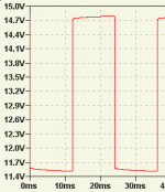
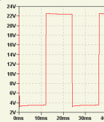
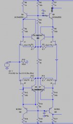
I have reporting how to catch MD - with square wave and good scope. It is done by fellows from some Russian forum. They also suggested SPICE models. Moreover, I have accomplished little research using these models. LTspice has opportunity to read and write wav files. The same musical fragments were processed with using of simple CE stage (BTW, it is right part of this picture: http://gaydenko.com/spectrum/case03/schematics.png ). Raw and MD-wrapped models were used. I have named result fragments with coin helpChrister said:Interesting. However, since we still don't know quite what MD is and if it exists, how do you know that MD is eliminated and that that is the reason for the good sound?
") to make test be blend. Almost all (if I remember well, about 90%) recipients have preferred raw-model fragments.
to make test be blend. Almost all (if I remember well, about 90%) recipients have preferred raw-model fragments.I see, such research can not claim to be "truly scientific". At any case, I have done something I can
As for me, I have not any doubt regarding do MD exists or not, and must we eliminate it or not.Anli,
My point is just that even if it possible, or even plausible, that it is MD you measure, you cannot be sure of that, can you? You do measure something which you can reduce by design. You cannot be sure what this something is or if it is the (single) reason for the (perceived) audible difference. Despite that, it clearly makes the amplifier more accurate and linear if you reduce this something, so it cannot hurt to do so, whether it is audible or not.
My point is just that even if it possible, or even plausible, that it is MD you measure, you cannot be sure of that, can you? You do measure something which you can reduce by design. You cannot be sure what this something is or if it is the (single) reason for the (perceived) audible difference. Despite that, it clearly makes the amplifier more accurate and linear if you reduce this something, so it cannot hurt to do so, whether it is audible or not.
It isn't possible, it is obviouslyChrister said:My point is just that even if it possible, or even plausible...
Anybody with good scope and square-wave oscillator can see something like on the picture. BTW, my own scope is too simple for such measurements. If your's one is good, it takes few minutes to catch MD.At any research at some point we correlate results and hypotheses. Isn't it common? Again - just do it to be sure.Christer said:... that it is MD you measure, you cannot be sure of that, can you? You do measure something...
Originally posted by Christer ... or if it is the (single) reason for the (perceived) audible difference. Despite that, it clearly makes the amplifier more accurate and linear if you reduce this something, so it cannot hurt to do so, whether it is audible or not.
Completely agree. It isn't possible to change one thing keeping others the same. And this is a problem
Attachments
anli said:
It isn't possible, it is obviously
At any research at some point we correlate results and hypotheses. Isn't it common? Again - just do it to be sure.
Yes, if there is sufficent theoretical backing behind the hypothesis to rule out other possible reasons for the same behaviour (to some degree of certainty). The behavior for the square pulse could also stem from som capacitive phenomenon, even if less likely.
I obviousl do not know how much thinking and investigation those russian guys have put into this. Maybe they have made a thorough investigation of possible causes. Have they written anything about it in english?
As you see, not even peufeu is convinced of MD even if he believes it exists.
Completely agree. It isn't possible to change one thing keeping others the same. And this is a problem
Quite a problem, and a problem too often overlooked by people, not least on this forum. How often do we not read about people making some modification for a specific reason and then being convinced this reason was the cause for a different sound, even if other things changed at the same time.
Look at time scale. Use LP filter. Use rise time few dozens uS.Christer said:The behavior for the square pulse could also stem from som capacitive phenomenon, even if less likely.
In Russian only, sorry...Christer said:I obviousl do not know how much thinking and investigation those russian guys have put into this. Maybe they have made a thorough investigation of possible causes. Have they written anything about it in english?
Christer said:Quite a problem, and a problem too often overlooked by people, not least on this forum. How often do we not read about people making some modification for a specific reason and then being convinced this reason was the cause for a different sound, even if other things changed at the same time.
Yes! And very often conclusions are very funny
And not at forums only, and not with sound only. Everywhere, everything...forr said:An other thought I had about the thermal distorsion is that, in a conventionnal differential input stage, current variations are very small at low frequencies, so the main thermal variations are due to the varying Vce voltages.
That is a good point forr, and at high frequencis where more current is needed, thermal distorsion would be less of a problem anyway dur to thermal inertial.
There is also another intersting observation one can make about the diff amp. Ic is a function of the differential voltage, but Vce is often primarily a function of the common mode voltage. That means that the temperature induced effects stem from the common mode voltage, which we don't want want to amplify and which is often several orders of magnitude larger than the differential voltage, that want to amplify. That is, the thermal distorsion is not even correlated to the signal we are amplifying in the general case! Fortunately, the usual topologies for audio amplifiers will probably not suffer from this, since common mode and differential voltage are so strongly correlated in these. However, the thermal distorsion would probably be stronger than expected for the reasons stated.
There is something that hasn't been mentioned within this thread but that was already discussed on this forum.
Not only semiconductors are temperature dependant but also resistors as we all know. It was mentioned that one shouldn't use "whimpy" resistors in feedback networks in order to keep thermal effects as low as possible.
Regards
Charles
Not only semiconductors are temperature dependant but also resistors as we all know. It was mentioned that one shouldn't use "whimpy" resistors in feedback networks in order to keep thermal effects as low as possible.
Regards
Charles
Charles,
I agree this should be considered too, and I was also thinking about whether it fits in this thread. I also think it does. There are at least two sources of nonlinearities in resistors, thermal effects and voltage dependece. I would expect the voltage dependence to be instantaneous, though, so that is probably not a case of memory effects. The thermal effect most likely is a case of memory in the sense we are discussing here. However, I would expect a resistor to have different type of thermal behaviour than transistors, the thermal time constants being spaced less apart. That is just a guess, however, and we would still have some form of delay. The voltage variations in a resistor should also cause a 2nd harmonic due to power variations.
The feedback resistor is interesting to consider since the feedback network and the input summing (or subtraction node, like the diff amp) are the two parts of the nfb loop that cannot be corrected by the loop. That is, errors in those will not be reduced. For that reason, I also expect memory distorsion in transistors to be most problematic in the input stage (if a problem at all). Some designers, ie. Pavel Dudek, already take the heat in the feedback resistor into consideration and use several parallel resistors to keep down the power dissipation in each.
Yes, also the feedback resistor is the one that takes the highest voltage swing since it handles the output of the power amp.
I believe resistors would have slower time constants since the mass is larger. Tempcos are mentioned in the datasheets... this could be measured, too.
I tried some simulations or transistor memory effects, but so far nothing spectacular. There is no good way to simulate hFE drift wrt temperature, which is the important parameter for the VAS.
You can also find thermal effects in output stages : temperature variation in the output transistors will change the idle current bias, and hence, the crossover distortion spectrum. Therefore, after a kick drum blast for instance, output transistors are hotter, thus idle current is larger.
Dielectric absorption is also a form of memory. I believe this matters for the amplifier Cdom cap, for instance.
Hi,
About the non-linearity of the components in the feedback network,
some discussion starting post #50, here :
http://www.diyaudio.com/forums/showthread.php?postid=867174#post867174
About the non-linearity of the components in the feedback network,
some discussion starting post #50, here :
http://www.diyaudio.com/forums/showthread.php?postid=867174#post867174
Hi Phase-Accurate,
For once, it is very easy to measure the effects of thermal cofficients. by runing the amp at low and high volumes and measure the voltage gain. Counteracting them is quite easy too, let's choose the right resistors (1 or 2 W for high thermel inertia, low tempco) for the feedback network.
For once, it is very easy to measure the effects of thermal cofficients. by runing the amp at low and high volumes and measure the voltage gain. Counteracting them is quite easy too, let's choose the right resistors (1 or 2 W for high thermel inertia, low tempco) for the feedback network.
Counteracting them is quite easy too, let's choose the right resistors (1 or 2 W for high thermel inertia, low tempco) for the feedback network.
I fully agree on that. It is what I meant with not using whimpy resistors.
I am not sure however if every designer is paying attention to that.
Regards
Charles
Hi Phase-Accurate,
---I am not sure however if every designer is paying attention to that.---
Some are since a long time. In the 1984 Siliconix MOS power applications book, Bob Cordell said :
"The resistance of this [feedback] divider was choosen to avoid noise and maintain good high-frequency characteristics. As a result, current flow and dissipation is not insignificant (100 mW in R12 [4220 Ohm from the output, the lower arm resistor is 215 Ohm, the overall voltage gain being about 20] at 50-watt operating level. To avoid thermally induced distorsion at low frequencies, there resistors should be oversized, 1-watt and 2-watt respectively."
Hi, PhaseAccurate,
I'm very interested in the 1w/2w feedback divider resistor requirement. Is this affecting sound quality? At first I tought the bigger resistors (2w) has bigger inductance than SMD resistors, so I choose SMD resistors.
Now I'm using 1206 SMD resistors for my UcD clone. The feedback divider is 12k/1k5. Is this bad? Should I change these feedback resistors to ordinary type 2w?
You can use several SMD ones in parallel in order to increase dissipation capability and further reduce inductance at once.
I am not sure however - but I assume that through-hole and SMD resistors of the same dissipation capability might have different thermal time-constants.
Regards
Charles
I am not sure however - but I assume that through-hole and SMD resistors of the same dissipation capability might have different thermal time-constants.
Regards
Charles
Pavel Dudek loves parallell resistors. Everywhere!
http://sjostromaudio.com/dudek_files/PA03_00.pdf
It seems sensible to use several small parallel resistorsrather than one big. First you can more easily find 1 % metal film in small wattage and seconly the total inductance will be lower (especially if the single big one would be wire wound).
http://sjostromaudio.com/dudek_files/PA03_00.pdf
It seems sensible to use several small parallel resistorsrather than one big. First you can more easily find 1 % metal film in small wattage and seconly the total inductance will be lower (especially if the single big one would be wire wound).
Hi,
I'm referring to post #9.
Imagine version B but with FET input pair. What would be reasonable working conditions for the Q's?
Whatever I do, LTSpice shows me sometimes more, sometimes less ringing, but never a square wave so clean as with a conventional input pair, *when applying a following stage like a VAS or a Folded Cascode*.
Is it a bandwidth issue? A cfp push-pull diff pair I'm simulating has -3dB at 4MHz (taken from one drain) according to the sim, a folded cascode gain block 3Mhz (open loop)
Some light shed on that issue would be much appreciated...
Rüdiger
- Status
- This old topic is closed. If you want to reopen this topic, contact a moderator using the "Report Post" button.
- Home
- Amplifiers
- Solid State
- Memory Distortion? and some new beginnings.