I presume you mean the Vce ? Yes, if you use a constant power stage, obviously.
If Vce does not vary, and Ic is constant, then obviously Vbe does not vary either. I meant Vbe, in fact. Since in an LTP the common reference devolves to the conjoined emitters, then constant Vbe for all signal conditions mandates a linear transfer function.
I am thinking intuitively without math modelling, but if this issue is solved, and I'm confident it can be, then thermal and other transistor action distortions could be wholly eliminated. This will bring more linearity to the input stage of an audio amplifier and thus rely less on GNFB to reduce non-linearities.
Cheers,
Hugh
AKSA said:
If Vce does not vary, and Ic is constant, then obviously Vbe does not vary either. I meant Vbe, in fact. Since in an LTP the common reference devolves to the conjoined emitters, then constant Vbe for all signal conditions mandates a linear transfer function.
I am thinking intuitively without math modelling, but if this issue is solved, and I'm confident it can be, then thermal and other transistor action distortions could be wholly eliminated. This will bring more linearity to the input stage of an audio amplifier and thus rely less on GNFB to reduce non-linearities.
Cheers,
Hugh
You make me puzzled Hugh. Except for second-order effects like the Early effect and thermal effects, Ic cannot change unless Vbe does. That is, if you want to use the transistor for amplification at all, you must vay Vbe. You cannot really speak of a transfer function for constant Vbe, since the transfer function describes how Ic changes when Vbe changes. So I do not understand what you mean here by a linear transfer function.
As a reminder, the transfer function for the BJT is (somewhat simplified)
Ic = Is*e^(Vbe/Vt)
where Is a device dependent constant and Vt is the thermal voltage which is also a constant. More precisely, they are only constants for a fixed temperature, since they are both temperature dependent.
The equation can be rewritten as follows, whenever more suitable
Vbe = Vt*ln(Ic/Is)
First of all the part of the total distortion that is caused by the thermal changes seems to be beging compared to the rest.
If someone uses a double transistor with common die for the LTP this should definitely be reduced. Most of the times these double transistors were intentionally designed to have good thermal coupling (in order to minimise thermal drift in critical analog circuits.).
I assume that the thermal properties must also be very good for OP-AMPs, even for mediocre types.
Regards
Charles
Hi,
Let's imagine a virtual bipolar with a constant Vbe and its emitter degenerated by a resistor connected to 0V. Any change in the base voltage (ref 0V) will change the voltage across the emitter resistor, then the current variations will follow a very linear law. Such an ideal device will generate no distorsion but does not exist.
However, if there is a circuit ahead of the base which maintains a constant voltage difference between its input and the emitter, we do have a composite amplifying device which is extremely linear.
What can be the added circuit ? We all know it : a negative feedback circuit. This is what I previously refered to :
---Perrot has disregarded one of the input gain stages he studied. It is as linear as his patented circuit, and contrarily to it, is not sensitive nor to temperature neither to input offset.---
It could be that the added input circuit needs a bootstrapped power supply referenced to the emitter.
An other thought I had about the thermal distorsion is that, in a conventionnal differential input stage, current variations are very small at low frequencies, so the main thermal variations are due to the varying Vce voltages. These variations are large in non-inverting configuration and much smaller in inverting configuration. Is there any visible difference (not to say audible) between the two at very low frequencies ?
AKSA said:
I do understand your reasoning; but I am not envisaging the LTP devices as amplification devices, merely as impedance transformers.
If you PM me, I will explain in more detail.......
Now I really wonder what you are up to.
")
It seems your profile is set up not to accept forum mail, though, and I am afrarid I have lost your email address since we last had contact. Could you please either change the setting or send me a mail I can reply to.
Since the previous FFT charts were done at one frequency only, 100 Hz, and the thermal effect is filtered, I deicded to check a few other frequencies too. I won't post the charts, but just remark on the findings. I already noted that for the previous test signal of 100 Hz, there was almost no difference in total distorsion with and without thermal effects, so the thermal distorsion was probably swamped by the other distorsion. Not surprisingly, we get the same result for 10kHz. However at 10 Hz, the 2nd order harmonic is about 10 dB higher with thermal distorsion than without, while the higher harmonics are the same. The same holds for 1 Hz. These are probably the results that should have been expected. Thermal effects will be more pronounced at lower freuqencies, due to the thermal inertia which filters the temperature changes. It also shows the thermal distorsion is predominantely 2nd order.
Do note, however, that the FFT analyses apply only to steady state and has little or unclear relationship to the transient thermal effect discussed before.
Do note, however, that the FFT analyses apply only to steady state and has little or unclear relationship to the transient thermal effect discussed before.
If I understood some of the linked site's postings, it claimed that the more gain a stage has i.r.t the input signal the more it amplifies the thermal distortion... could you explain this a bit better?
Also what do we think of thermal drifts being proportional with music signal amplitude? and its implications...
Also what do we think of thermal drifts being proportional with music signal amplitude? and its implications...
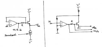
OK, time to get a reality check. Here are two proposals for measuring the thermal behaviour of a simple transistor.
This will need a soundcard capable of DC, ie for instance an old Soundblaster with all coupling capacitors removed.
Since a transistor has 3 terminals, we have 2 currents and 2 voltages to set or measure. Say : Vce, Vbe, Ib, Ic. Ic and Ie are interchangeable. We can set 2 of those, and measure the other two, so this leaves 6 permutations :
- set Vbe, Vce, measure Ib, Ic
Problem : setting Vbe needs careful adjustment to avoid thermal runaway. Thus, bad configuration.
- set Vbe, Ib, measure Vce, Ic
- set Vce, Ib, measure Vbe, Ic
- set Ib, Ie, measure Vce, Vbe
Those three need a very precise current source to set Ib. I think it is a lot easier to measure Ib than to set it to a chosen value.
- set Vbe, Ie, measure Vce, Ib
Needs instrumentation amps with high precision.
- set Vce, Ie, measure Vbe, Ib
Easiest choice.
#1 : A current source, controlled by the soundcard output, sends current through the transistor. An opamp holds the base of the transistor at a virtual ground potential. Therefore we can measure base current as a voltage in resistor R, and simply measure Vbe as Ve (since Vb = 0).
Pros :
- no need for instrumentation amp
- simple
- Vce is constant (one less variable to consider)
Cons :
- needs a good VCCS with high PSRR (maybe not that hard to do)
#2 : The transistor is used as an inverting amp, comtrolled by an opamp.
Pros :
- simpler
Cons :
- depends on the power supply precision (BAD !)
---------------
So, I prefer the first solution. Also, the other output channel of the soundcard could be used to control Vce, making it also a full transistor curve tracer.
A good voltage controlled current source is needed, with high PSRR, and of course, no thermal tails in itself.
Attachments
Why most of you think about MD essentially in terms of linearity (THD measures, FFT…) and not in terms of time domain errors, like an add-on signal “thermal mirror” of the input signal delayed by a few mS (thermal constant) ? The ear can accommodate with a certain amount of THD or even IMD but what about a superimposed delayed signal?
Justcallmedad said:Why most of you think about MD essentially in terms of linearity (THD measures, FFT…) and not in terms of time domain errors, like an add-on signal “thermal mirror” of the input signal delayed by a few mS (thermal constant) ? The ear can accommodate with a certain amount of THD or even IMD but what about a superimposed delayed signal?
Richard,
I'm completely here with you!
I have tried to say about time-fragment correlations and such, but nobody is interested in. I have tried to say about estimating MD on some another way rather THD/IMD, but nobody is interested in. The same with audio-chain behaving at infra-low frequencies. Well, not being an EE, I can not insist on breaking of traditional ways. Nevertheless, for me it seems like it is very difficult for fellows to look at something from non-standard POV

Justcallmedad said:Why most of you think about MD essentially in terms of linearity (THD measures, FFT…) and not in terms of time domain errors, like an add-on signal “thermal mirror” of the input signal delayed by a few mS (thermal constant) ? The ear can accommodate with a certain amount of THD or even IMD but what about a superimposed delayed signal?
Well, I don't know if we do think of it that way, but of course we try to use the tools and the terminology we have to see where it takes us. It seems this may be a phenomenon we cannot thoroughly understand either in that way, or in the way you suggest.
As I suggested earlier, and as my simulation experiments seem to confirm, the thermal distorsion consists of a fundamental and a 2nd harmonic (the latter not always present). They can be phase shifted wrt. the signal. However, the phase shift is frequency dependent, so it does not correspond to a fixed time delay either. Furthermore, when the 2nd harmonic is present, the thermal distorsion is no longer only mirroring the signal with a delay.
Look at the transient simulations I did. We clearly cannot just make an FFT to understand what is happening (the FFTs I did was for the steady state only, not for transients). But it seems equally clear we cannot understand it as only a scaled and delayed copy of the signal.
Anli,
I didn't see your latest post until after posting this. As you see, I do agree with you, if not about a specific method, so at least that we may have to look at it somewhat differently.
Yeah, all the D's (THD, IMD, etc) only consider steady state signals... thermal effects are different.
I don't think it would manifest itself as a time-delayed copy of the signal (like an echo) because a single transistor isn't like a reverb line or a delay line, from the past it only keeps one value, its temperature. So, it can't delay the signal and then replay it...
However, I've always wondered about how gear can affect our perception of rythm. You know, how some gear feels faster, slower, moves your feet or bores you. I'm pretty sure there are a lot of psycho-acoustic reasons, but maybe we should look into physical phenomena having time constants in the order of human-noticeable (ie. > 20 ms), which includes thermals, but also PSU pumping effects, microphony (esp. in CD players), cabinet resonance, etc.
Christer : looked at my proposal for measuring stuff on last page ?
Yes, yes and Yes!Originally posted by peufeu ... but maybe we should look into physical phenomena having time constants in the order of human-noticeable (ie. > 20 ms)...
The thing is, psycho-acoustics keeps silent (at least, I have not found something useful wrt MD).anli said:
Yes, yes and Yes!
Psychoacoustics is also important, that is a whole different kettle of fish. It is one thing to figure out if thermal memory distorsion exists and how to characterize it. That is electronics and math. It is a different thing to figure out if we can hear it and how it sounds. That is psychoacoustics (well, and audiology too).
We may still not know enough about how to measure amplifiers (I say "may", since opinions vary on this), but we know even less about psychoacoustics.
For now we, or I at least, concentrate on the first part, trying to figure out if the problem exists and what it is like. When I say "if the problem exists" I mean if it can arise at all in common circuits, not if it is a common problem. I think we already know how to get around the problem, or at least reduce it. What we don't know if there is a need for doing that.
peufeu said:
Christer : looked at my proposal for measuring stuff on last page ?
Yes, but it seems to be "just" at setup for measuring transistors. The interesting thing is how you suggest measuring MD with it. We still have no way to access the temperature of the transistor, so any measurement must be indirect in some way.
Yes we have. Vbe at a known Ic / Vce makes a nice thermometer.
Imagine this (like in the other doc I posted about transistor measurement)
- transistor is at ambient temperature
- set Vce, Ie to a know state
- wait for thermal equilibrium (heating transistor case... maybe 10 minutes)
- sample Vbe, Ib => Vbe0, Ib0
- set Ie to a much higher value
- sample Vbe, Ib continuously
- reset Ie to initial value
- sample Vbe, Ib => Vbe1, Ib1
Then, (Vbe1 - Vbe0) divided by 2 mV/°C gives you deltaT. You know the pulse width and the delta power, you can estimate thermal capacity.
Doing this enough times with various pulse widths, and then fitting, could give you a thermal model.
> The interesting thing is how you suggest measuring MD with it
I don't. I just want an accurate model, as a starting point. We don't even know what MD is right now...
I think, time-correlated fragments, musical instruments attack importance and such are inside psychoacoustics also, rather different single tone thresholds.Christer said:Psychoacoustics is also important, that is a whole different kettle of fish. It is one thing to figure out if thermal memory distorsion exists and how to characterize it. That is electronics and math. It is a different thing to figure out if we can hear it and how it sounds. That is psychoacoustics (well, and audiology too).
And why must we measure with methods we use instead of to try to understand what we indeed need to measure?Christer said:We may still not know enough about how to measure amplifiers (I say "may", since opinions vary on this), but we know even less about psychoacoustics.
Christer said:For now we, or I at least, concentrate on the first part, trying to figure out if the problem exists and what it is like. When I say "if the problem exists" I mean if it can arise at all in common circuits, not if it is a common problem. I think we already know how to get around the problem, or at least reduce it. What we don't know if there is a need for doing that.
I have referenced two myself soldered (and under using) amps with eliminated MD - nobody noted something like so called "transistor sounding". Being very good measuring, the amps are melodious also. This is opinion of tube-fans also
OK, I see, it is my (and my friends) own subjective experience. At any case, I think, it is worth to try those simple (or other) methods of reducing power dissipation deviation and, at least, to spread subjective experience.
(saying about eliminating MD, I mean those amp parts which are beyond NFB loop, if even last one is short like in (modified) cfp, as is in my cases).
anli said:
I think, time-correlated fragments, musical instruments attack importance and such are inside psychoacoustics also, rather different single tone thresholds.
Yes, and all that is very interesting and important for how we perceive sounds and music. It also very important for compression technologies like mp3. However, it is not clear that any new such concepts or measurements methods for audio equipment are needed. We see that perhaps MD and certain other transient phenomanae might require something more than the usual methods. Yet, even if they do, it might be the case that it does not matter for our perception anyway.
And why must we measure with methods we use instead of to try to understand what we indeed need to measure?
The traditional assumptions is that what we measure with the traditional methods reveal everything there is to know about the audio equipment. There is quite rigorous mathematics behind the theorems of systems theory and electronics.That we know how to measure everything that is relevant is not an undisputed assumption, however. I think what we are trying to do in this thread is precisely what you suggest, trying to figure out how to measure MD and if it exists. But how it sounds is a different issue from measuring.
I have referenced two myself soldered (and under using) amps with eliminated MD - nobody noted something like so called "transistor sounding". Being very good measuring, the amps are melodious also. This is opinion of tube-fans also
OK, I see, it is my (and my friends) own subjective experience. At any case, I think, it is worth to try those simple (or other) methods of reducing power dissipation deviation and, at least, to spread subjective experience.
(saying about eliminating MD, I mean those amp parts which are beyond NFB loop, if even last one is short like in (modified) cfp, as is in my cases).
Interesting. However, since we still don't know quite what MD is and if it exists, how do you know that MD is eliminated and that that is the reason for the good sound?
peufeu said:Yes we have. Vbe at a known Ic / Vce makes a nice thermometer.
True. If we don't explicitly set Vbe then yes, quite right. I overlooked that. That makes your first circuit quite clever indeed. I vote for that one too.
Imagine this (like in the other doc I posted about transistor measurement)
- transistor is at ambient temperature
- set Vce, Ie to a know state
- wait for thermal equilibrium (heating transistor case... maybe 10 minutes)
- sample Vbe, Ib => Vbe0, Ib0
- set Ie to a much higher value
- sample Vbe, Ib continuously
- reset Ie to initial value
- sample Vbe, Ib => Vbe1, Ib1
Then, (Vbe1 - Vbe0) divided by 2 mV/°C gives you deltaT. You know the pulse width and the delta power, you can estimate thermal capacity.
Doing this enough times with various pulse widths, and then fitting, could give you a thermal model.
Yes, sounds good to me. 2 mV figure is just a rule of thumb, of course, but is probably good enough for the purpose, as is the linear approximation for temperature dependence if we don't vary the temperature too much.
- Status
- This old topic is closed. If you want to reopen this topic, contact a moderator using the "Report Post" button.
- Home
- Amplifiers
- Solid State
- Memory Distortion? and some new beginnings.