Imho, the problem of the method is, as you have mentioned somewhere, and as i have been experimenting myself, the curves bend very soon on the left probably because of the use of short time windows. This is a major issue if your acoustic environment makes this windowing necessary to avoid refexions.
This will limit its use, mainly to tweeter/mid offset estimates. For me it'is ok in this case because it's a quick and easy way to get some input, to contrast with some other or some guess, and precision is not really an issue.
This will limit its use, mainly to tweeter/mid offset estimates. For me it'is ok in this case because it's a quick and easy way to get some input, to contrast with some other or some guess, and precision is not really an issue.
I went back to the OP. Your first sentence was:The original topic was a method of measuring relative acoustic centre offset between two particular drivers in a single measurement. Perhaps the thread topic could have been worded a bit better but I think that intent is clear in my original post.
I disagree. There are ways to do it that are not only relatively easy, but highly accurate. I can get down to the 0.1mm if I care to go that far, though it has to be said that it's for a specific set of driver models to be used in design and for a specific axis. But I also have yet to see any method that is highly accurate in actually determining relative acoustic offset that does not require creation of a model. In any case, there is free software for both measuring and modeling that can be used and they are accurate when used properly.Something that is sometimes desirable is a method for determining the relative acoustic offset of two drivers in a multi-way system, and most of the methods I've seen that are open to a DIY'er aren't that accurate or easy to do.
Your sixth paragraph states:
With all due respect, I believe that this is far less accurate for reasons covered previously, sample rate being largely determinant.A better approach is to measure the impulse response of each driver independently and compare the arrival time differences at a microphone whose height is equidistant between the centre of each driver. By comparing arrival times in fractions of a millisecond a distance offset can be calculated.
Your later Arta point 2:
Not required for the method I describe. If one can make impulse measurements (dual or single channel) or only a stepped sine sweep such as LMS when I used it, it's possible to still get an offset accurate to better than a mm if desired. Three simple measurements at almost any point desired within reason is all that is required for high accuracy. Measured phase is not required. My experience has been, though, that MLS-based measurement is more repeatable. Just my experience.2) No need for dual channel measurement mode.
Later on you state:
It's not the thread wording. This sounds like it's for purpose of design to me.I'm only suggesting it as a possible method for midrange to tweeter crossovers as getting a long enough window time to measure a woofer to midrange crossover seems unlikely, however accurate measurement of small acoustic offsets at low frequencies isn't really necessary.
On that I fully agree.As you've pointed out previously an absolute measurement to a single driver is inherently going to have uncertainty that can't be avoided, however a relative measurement between two drivers when both drivers are measured summing together in the same measurement has the potential to be extremely accurate.
At the end of the day the relative delay is all that matters.
You misunderstood my point. If you design with direct measurements, all phase is included and there is no need to determine relative offset, it's inherent in the measurements, I meant nothing more than that.No relative offset ? Just because you might design the crossover to phase track through the overlap region doesn't mean there is no relative offset in the driver acoustic centres. Whether it matters or not is a separate discussion.
I have to disagree completely with the premise if by difference in delay you mean the precise amount of excess-delay difference between drivers. Otherwise you're simply talking about the delays of driver minimum phase, driver excess phase and crossover induced delay, all part of any measured "delay" in a system with a crossover.You're really trying to over-think the situation here. Why is the absolute centre location of each required to determine the difference in delay of the two drivers ? It's not. The single measurement of both drivers crossed over with each other can tell you that. That was the whole point of my original post.")
This did seem to be implicit to me in your OP first paragraph quoted above. I suspect that most people who desire to actually determine relative acoustic offset are doing so for purposes of design, not academic reasons.You seem to be seeing the discussion in this thread through the lens of "how does this help me using cad design software to model and design a speaker". Nowhere in my original post are there any assumptions about what will be done with the information, or that it would be used in any sort of cad software.
Dave
Last edited:
This did seem to be implicit to me in your OP first paragraph quoted above. I suspect that most people who desire to actually determine relative acoustic offset are doing so for purposes of design, not academic reasons.
Dave
Trying to determine relative acoustic offset is a mere academic question that arises from the design process. Trying to find the AC of a driver only makes sense depending on what you need the data for. The concept in itself is pointless.
If your technique is based on driver models rather than pure measurement, how can you confirm its accuracy ? Surely there are assumptions implicit in any model that simplifies reality ?I disagree. There are ways to do it that are not only relatively easy, but highly accurate. I can get down to the 0.1mm if I care to go that far, though it has to be said that it's for a specific set of driver models to be used in design and for a specific axis.
Well, have you tried the method I proposed ? Or are you just picking holes in it on theoretical grounds ? (Serious question, not flippant)But I also have yet to see any method that is highly accurate in actually determining relative acoustic offset that does not require creation of a model.
You've both quoted me out of context and taken the opposite meaning from what I've said.Your sixth paragraph states:
With all due respect, I believe that this is far less accurate for reasons covered previously, sample rate being largely determinant.
The sentence immediately following which you snipped off was "Many software measurement systems such as ARTA can do this, however there are some significant practical challenges to accurately measuring this way:"It's abundantly clear from what I wrote that I believe that comparing the time delay to start of impulse rise of two separate impulse measurements (a method often promoted) is far less accurate than the method I proposed, and I specifically stated sample rate granularity (+/- 1 sample error etc) as one of the reasons...
The problem with taking two separate measurements with any Windows PC based measurement system (including ARTA) is not related to whether its MLSS or swept sine (makes no difference really) its that unless you have seriously expensive sound card hardware and very well written device drivers (and even then) it is not possible to guarantee sample accurate input/output delay times for single channel measurements from one measurement to the next, as the delay time through the device driver stack in Windows is non deterministic. (It's affected by other software running on the computer, and on many sound cards every time the sound card device is initialized the total input/output loop delay can be slightly different)Your later Arta point 2:
Not required for the method I describe. If one can make impulse measurements (dual or single channel) or only a stepped sine sweep such as LMS when I used it, it's possible to still get an offset accurate to better than a mm if desired. Three simple measurements at almost any point desired within reason is all that is required for high accuracy. Measured phase is not required. My experience has been, though, that MLS-based measurement is more repeatable. Just my experience.
That means if you are measuring one driver in one measurement and the other in a separate measurement, there is always a degree of uncertainty about whether the measured time delay is sample accurate in delay or not. In single channel measurement mode there is a finite but unknown delay between the generation of the test signal before it goes into the DAC and the measured signal after its processed by the ADC.
This can be anywhere between about 2ms for a good sound card to 20ms for a poor one, also depending on device drivers (ASIO mode giving lower and more stable latency than WDM) but the point is the test software has no way of knowing what this delay is (other than an analog loopback test) or whether it is consistent from measurement to measurement.
The ARTA manual has this to say about it: "Theoretically, the averaging technique, from a dual channel system, can be applied in a single channel system, but due to the limitation of the Windows sound driver, which does not keep the synchronicity between the signal playback and recording, only the time domain synchronous averaging can be applied. The phase response can't be estimated with an absolute accuracy."
Single channel measurement techniques usually use heuristics to "look for" the first peak of the computed impulse response to use as a time reference, (remember the software doesn't know the total time delay of the driver/sound card) so that repeated measurements of the same system seem consistent despite varying delays in the sound hardware/drivers from measurement to measurement, however this can sometimes be fooled for example if you have a very slow rising impulse or one where there is no obvious first peak and a lot of ringing, sometimes it picks the "wrong" reference point in the impulse and the resulting phase response is wrong.
Dual channel mode gets around that by having one channel as a loopback so that delay variations can be measured down to the sample and cancelled out, but dual channel mode comes with its own limitations.
My point was that the technique I presented eliminated this source of error entirely, as there is only one measurement, so no chance of inter-measurement time delay errors. Everything needed is contained in the phase response of a single measurement.
Not necessarily. Where is the harm in knowing a piece of information without then using it to design something ? I really don't understand your point. This measurement technique makes it possible to relatively easily measure the delay between drivers in an already finished speaker (without any disassembly) as a matter of curiosity. Where is the harm in that ?It's not the thread wording. This sounds like it's for purpose of design to me.
Bear in mind that the excess group delay is just a visually more convenient representation of the excess phase, which itself is derived from actual phase measurements minus HBT minimum phase.You misunderstood my point. If you design with direct measurements, all phase is included and there is no need to determine relative offset, it's inherent in the measurements, I meant nothing more than that.
Same information, different visual representation. Looking at a raw phase curve to try to see time alignment is theoretically possible but practically not very usable since you're trying to assess the slope of a very long steep line.
Looking at group delay is not very useful because the group delay variations resulting from amplitude variations far outweigh (by an order of magnitude or two) the group delay variations caused by the actual physical delay. Using excess group delay eliminates that non-useful piece of information making clear in one easy to view measurement what needs to be known to compute the relative acoustic centre offsets.
That's exactly what I mean. Why do you disagree ?I have to disagree completely with the premise if by difference in delay you mean the precise amount of excess-delay difference between drivers.
Obviously the crossover will introduce an excess delay at the crossover frequency but sufficiently far from there it isn't a factor. "Sufficiently far" means that the other driver is far enough into its stop-band to not be contributing to the response.Otherwise you're simply talking about the delays of driver minimum phase, driver excess phase and crossover induced delay, all part of any measured "delay" in a system with a crossover.
Silly question maybe, but have you actually tried doing some experimental measurements using the described technique with ARTA on a few real world speakers to see how the results agree (or don't) with other methods ?
Because many of the objections you're raising really do make me think that you simply haven't tried it and are objecting to it purely on theoretical grounds without perhaps quite appreciating some of the finer details. Sometimes its easy to dismiss something without actually trying it for yourself.
Last edited:
Imho, the problem of the method is, as you have mentioned somewhere, and as i have been experimenting myself, the curves bend very soon on the left probably because of the use of short time windows. This is a major issue if your acoustic environment makes this windowing necessary to avoid refexions.
This will limit its use, mainly to tweeter/mid offset estimates. For me it'is ok in this case because it's a quick and easy way to get some input, to contrast with some other or some guess, and precision is not really an issue.
Yes the window length will limit accuracy at lower frequencies, but bear in mind that excess group delay is computed from excess phase, which is computed from measured phase minus HBT phase, so any more "conventional" phase measurements are going to have exactly the same errors.
You can't measure the absolute phase at low frequencies any more accurately than excess group delay if the window time is too short - that's not a fault of the excess group delay technique. It goes without saying that you must have a sufficiently long window time for any measurement to be useful, so yes, its mostly useful for midrange to tweeter crossovers in practical measuring environments, but it could be argued that small amounts of time delay between a woofer and midrange are not as important anyway.
On the design axis of course, usually on axis. (Unless you're Earl GeddesI agree, but what axis are we talking about?
)Only in the vertical plane, and only at the crossover frequency. It is not equivalent in the horizontal plane (since the acoustic centre offset will vary with horizontal angle) and nor is it equivalent on either side of the crossover frequency. (Since the slopes are different than a zero offset equal slope design, and real world high frequency and low frequency drivers have different dispersion characteristics that come into play on either side of the crossover point)If we mount a classical 1' TW and a classical 7' W on a flat baffle with an LR design in mind, this is considered a non aligned system. Well, we should modify this statement because the drivers will not be aligned for an horizontal axis between the drivers, but you will always find an axis along which the drivers will be aligned, the only concern is that this axis might be badly tilting downwards, making the speaker difficult to use, but this axis exists and the amplitude response we measure on it is flat. The real problem is that the vertical polar response of this arrangement will be badly degraded compared with the one you get when the main lobe is horizontally flat.
If we then change the polarity of the tweeter, the result will be similar, but the new axis will be shifted upwards, and the polar response will be degraded compared to the ideal one, but in a different way.
Anyway, by tweaking the slopes, for instance increasing the tweeter's side, the result will be bringing up ( or down with flipped polarities) the orientation of the main lobe, and the result will be a polar behaviour more conform to a textbook LR behaviour.
Again, only in the vertical plane.The right amount of tweaking is the one which allows the closest match to the LR target, both on and off axis.
And of course, similar changes in the polar response can be obtained by applying delay.
Adding delay or bending the phase to "fix" the vertical polar lobe directions is not the same as physically offsetting the driver for horizontal polar response, another often overlooked difference is that having one driver closer or further than the other means that the inverse square law falloff for the two drivers doesn't track properly with variations in listening distance.
As you get closer to the speaker the driver which is too close increases in level faster than the driver that is further away.
If it is the tweeter that is too close, as is usually the case this compounds the problem where the larger low frequency driver is transitioning from point source to plane source as you approach the speaker and is already not increasing in level as much as the tweeter which more closely approximates a point source at the same distance.
Sorry but no matter how much you guys try to convince me, adding digital delay is only the same as adding physical delay for the on axis response, and (somewhat) in the vertical plane, it is not equivalent in a number of other ways including the two just mentioned.
Bending the phase for phase tracking of offset drivers is also not equivalent in even more ways than adding delay. If amplitude response on axis is the only target then fine, but it is frustrating when people are so dismissive of some of the finer details and are quite happy to accept without question that summed amplitude response on axis is all that really matters...
Most important ? Probably. The whole story ? No.
Last edited:
Any truncation errors will create corresponding phase errors. That is the frequency response and phase curve will always match and if one is off the other will be similarly off. The measured phase will be essentially the Hilbert Tranform phase of the erronious response curve, plus an actual delay as appropriate. Still, your primary use for woofer phase is in matching the upper phase curve to the lower phase curve of the midrange. Truncation error has no effect at the top end of the woofer so your phase in that regions should be quite accurate.
David S.
David S.
As long as the input and output stream is kept alive (HolmImpulse terminology), there is a guaranteed time synchronity on windows systems for any record-while-playback situation. Otherwise ANY record-while-playback would not be possible at all.
Some care is needed, though. Don't stall the system, don't reconfigure the I/O etc.
HolmI allows access to the test signals (I gave Ask a hard time, begging him to impement this), so you can add a synchronizing pulse before the sweep, record it externally and the crop any delay manually (which always is a integer multiple of samples) in case you ever need to stop the I/O between measurements for whatever reason.
Acourate does even something more elaborate allowing to use non-sample-synchronous recording (eg if the sweep comes from a CD-player), again using marker pulses before and after the sweep in order to adapt the sweep's inverse prior to convolving.
The three measurement method does not have any of the problems listed. The phase is irrelevant, impulse timing is not an issue, the only requirement is SPL magnitude. Verification of design against final system measured response is very accurate. It's also very accurate using SoundEasy with any number of sound cards, though my preference is still for my Liberty Instruments LAUD system purchased in 1998 that uses a DSP card for all sampling that is then uploaded at the end of sampling to the PC. But even LMS with its swept sine will work. That's the point, there is nothing special required, it's straightforward, reliable and very repeatable.My point was that the technique I presented eliminated this source of error entirely, as there is only one measurement, so no chance of inter-measurement time delay errors. Everything needed is contained in the phase response of a single measurement.
There's no harm of course. I've simply taken issue with repeated claims of it being difficult to measure acoustic offset, repeated in your post here, that is simply wrong.Not necessarily. Where is the harm in knowing a piece of information without then using it to design something ? I really don't understand your point. This measurement technique makes it possible to relatively easily measure the delay between drivers in an already finished speaker (without any disassembly) as a matter of curiosity. Where is the harm in that ?
Yes, BUT, what is HBT minimum phase? It is a calculated phase based upon an assumption of the SPL response because assumptions have to be made about the SPL response beyond the stop band and will at times be dependent upon data withing the passband that may be approaching the noise floor or have high pass data that has insufficient sample points. Any and all excess phase determinations are based upon one or more assumptions. That's why determining absolute center always has had uncertainty. Any measurement that must explicitly use HBT phase in some absolute way will have uncertainty. If you're claiming that the measurement result is pure excess phase, I have to take issue with that.Bear in mind that the excess group delay is just a visually more convenient representation of the excess phase, which itself is derived from actual phase measurements minus HBT minimum phase.
You mention the Arta manual on averaging, but that' not relevant. Averaging has nothing to do with this and is not required. However, I can and in fact always do use averaging. LAUD has the capability of doing multiple measurements and averaging the responses that helps to improve S/N. Since it offloads all control during any measurement to the DSP card, there's no issue in so doing. But that's a digression, really also not relevant to the discussion, except that I can better S/N than a system without averaging. Overlay testing has shown that a single measurement and averaged response is usually nearly identical if the signal level is sufficiently high.
For the single reason that no measured excess group delay can be considered accurate. It is an approximation based upon assumptions.Looking at group delay is not very useful because the group delay variations resulting from amplitude variations far outweigh (by an order of magnitude or two) the group delay variations caused by the actual physical delay. Using excess group delay eliminates that non-useful piece of information making clear in one easy to view measurement what needs to be known to compute the relative acoustic centre offsets.
That's exactly what I mean. Why do you disagree ?
No I have not. I do not see anything that makes be believe that it can be accurate. If that can be proven, I'll be glad to see that. But I'm not looking to prove that something works that my understanding of theory says will not. If I'm proven wrong, no problem.Because many of the objections you're raising really do make me think that you simply haven't tried it and are objecting to it purely on theoretical grounds without perhaps quite appreciating some of the finer details. Sometimes its easy to dismiss something without actually trying it for yourself.
This is why I always make a point to say that even the method I describe can only be used for the set of models created because it has to be based upon assumptions related to each driver's SPL response. The key aspect is that the measured summed response has no assumptions concerning relative offset. Measured sum is accurate to the accuracy of the measurement system. But it is fully sufficient for design purposes with easily verified results. Matching to within 0.5db is possible, probably better if one really wants to work at it.If your technique is based on driver models rather than pure measurement, how can you confirm its accuracy ? Surely there are assumptions implicit in any model that simplifies reality ?
Dave
Last edited:
A synchronising pulse is a nice idea in theory, but what is the spectrum of the "pulse" ? Once your "pulse" has passed through a system that is introducing group delay, then what happens to the time accuracy of your pulse as a reference ? Which frequency components form the reference time ?HolmI allows access to the test signals (I gave Ask a hard time, begging him to impement this), so you can add a synchronizing pulse before the sweep, record it externally and the crop any delay manually (which always is a integer multiple of samples) in case you ever need to stop the I/O between measurements for whatever reason.
It's not quite as simple as adding a reference pulse as far as I can see, when the system under test has significant group delay variations with frequency that will distort the pulse.
Also how do you know that the delay is always an integer number of samples ? That assumes that the ADC and DAC are clocked on the same clock using the same clock phase, not necessarily a safe assumption on cheaper cards.
Also, any "manual" cropping of the impulse based on visually looking at it reintroduces +/- 1 sample errors, something I was specifically trying to avoid.
On the design axis of course, usually on axis. (Unless you're Earl Geddes
Only in the vertical plane, and only at the crossover frequency. It is not equivalent in the horizontal plane (since the acoustic centre offset will vary with horizontal angle) and nor is it equivalent on either side of the crossover frequency. (Since the slopes are different than a zero offset equal slope design, and real world high frequency and low frequency drivers have different dispersion characteristics that come into play on either side of the crossover point)
Again, only in the vertical plane.
Adding delay or bending the phase to "fix" the vertical polar lobe directions is not the same as physically offsetting the driver for horizontal polar response, another often overlooked difference is that having one driver closer or further than the other means that the inverse square law falloff for the two drivers doesn't track properly with variations in listening distance.
As you get closer to the speaker the driver which is too close increases in level faster than the driver that is further away.
If it is the tweeter that is too close, as is usually the case this compounds the problem where the larger low frequency driver is transitioning from point source to plane source as you approach the speaker and is already not increasing in level as much as the tweeter which more closely approximates a point source at the same distance.
Sorry but no matter how much you guys try to convince me, adding digital delay is only the same as adding physical delay for the on axis response, and (somewhat) in the vertical plane, it is not equivalent in a number of other ways including the two just mentioned.
Bending the phase for phase tracking of offset drivers is also not equivalent in even more ways than adding delay. If amplitude response on axis is the only target then fine, but it is frustrating when people are so dismissive of some of the finer details and are quite happy to accept without question that summed amplitude response on axis is all that really matters...
Most important ? Probably. The whole story ? No.
A multiway extended source will never behave as a point source. We have to learn to live with offsets... without offsetting ourselves unecessarily...
I think I've responded to this point way back in the thread - if your idea of "easy" is creating a full model of the drivers in a cad package and taking 3 separate measurements then so be it.There's no harm of course. I've simply taken issue with repeated claims of it being difficult to measure acoustic offset, repeated in your post here, that is simply wrong.
That's certainly not the method that most DIY'ers will attempt, and its a lot of work to determine acoustic centre offset compared to taking a single measurement that can be done in a matter of a couple of minutes. So yes, I say that most other methods if not difficult are at the least either time consuming (yours) or prone to error. (comparing the absolute delay to impulse rise of two separate measurements)
Of course there is uncertainty if there isn't sufficient measurement bandwidth, but there must be no matter what method you are using, including yours. You can't manufacture accuracy out of lack of data.Yes, BUT, what is HBT minimum phase? It is a calculated phase based upon an assumption of the SPL response because assumptions have to be made about the SPL response beyond the stop band and will at times be dependent upon data withing the passband that may be approaching the noise floor or have high pass data that has insufficient sample points. Any and all excess phase determinations are based upon one or more assumptions. That's why determining absolute center always has had uncertainty. Any measurement that must explicitly use HBT phase in some absolute way will have uncertainty. If you're claiming that the measurement result is pure excess phase, I have to take issue with that.
With the excess group delay method its easy to determine the limits of accuracy though - simply measure the excess group delay of an individual driver with its minimum phase crossover section. (Other driver disabled) We can pretty much assume that any reasonable driver is going to be minimum phase at low frequencies, and a normal crossover section is also minimum phase, so we know that what we should see for excess group delay is a flat line.
When we see that flat line start to curve upwards at low frequencies we know that we're now in an area where accuracy is suffering because of mis-estimation of excess phase for the reasons you describe. (Lack of measurement bandwidth to estimate HBT minimum phase etc)
We know then to exclude this range from measurement, (I cropped it off on the left hand side of the measurement in my original post, below the cropping point it started to curve upwards) or that we need a longer window time.
This measurement of one driver can also be overlaid over the measurement taken with both drivers active at once to confirm within which frequency range we should be sampling the delay of that driver. (Although its usually pretty obvious)
You missed the point of the quote from the ARTA manual, it was to point out that precise synchronisation (and repeatable sample accurate delay) between input and output streams on windows sound cards is not guaranteed, thus absolute phase accuracy is not possible with a single channel measurement.You mention the Arta manual on averaging, but that' not relevant. Averaging has nothing to do with this and is not required. However, I can and in fact always do use averaging.
As far as I can see, as long as the measurement bandwidth is sufficient the accuracy is no worse than any other measurements derived from an impulse in impulse based measurement systems...For the single reason that no measured excess group delay can be considered accurate. It is an approximation based upon assumptions.
Well again, its easy enough to take a few measurements on systems that you've already modelled with your own methods and compare them. I can't do that because I don't have access to your models. If you're not interested thats fine.No I have not. I do not see anything that makes be believe that it can be accurate. If that can be proven, I'll be glad to see that. But I'm not looking to prove that something works that my understanding of theory says will not. If I'm proven wrong, no problem.
While the method I've described makes no particular assumptions about the amplitude response of the drivers, in fact they don't even need to be known, really, since we're only looking at the excess delay.This is why I always make a point to say that even the method I describe can only be used for the set of models created because it has to be based upon assumptions related to each driver's SPL response.
Last edited:
You'll look at it in the time domain. Admittedly I forgot to mention that the pulse must come from the same driver each time, that means you need to switch to the driver to measure after the pulse when it is not the same. Or you use a paralleled and dimmed extra driver that is way closer to the mic, instead of using a marker pulse, that's even easier and doesn't need fiddling, just align this driver pulse response to the same point in time. The soundcard I'm using has quite some electrical leakage from output to input (think dimmed loopback), so I can even used that pre-pulse for alignent. Essentially you'll get a repeatable relative reference, no matter how it looks like and how you derive it as long as it is repeatable.A synchronising pulse is a nice idea in theory, but what is the spectrum of the "pulse" ? Once your "pulse" has passed through a system that is introducing group delay, then what happens to the time accuracy of your pulse as a reference ? Which frequency components form the reference time ?
It's not quite as simple as adding a reference pulse as far as I can see, when the system under test has significant group delay variations with frequency that will distort the pulse.
Any soundcard and/or audio-interface on this planet I'm aware of uses one single synchronous clock for all channels, and any OS handles audio streams I/O in multiples of full samples since there is no other way (as does any PCI bridge chip, USB/Firewire-PHY etc. How do I know? I used to design gear with this kind of stuff). Except for real chip or firmware bugs you are safe here, perhaps unless there's some crude resampling at work etc, but that can sorted out.Also how do you know that the delay is always an integer number of samples ? That assumes that the ADC and DAC are clocked on the same clock using the same clock phase, not necessarily a safe assumption on cheaper cards.
Zoom in properly before overlay/compare, to avoid this kind of user error.Also, any "manual" cropping of the impulse based on visually looking at it reintroduces +/- 1 sample errors, something I was specifically trying to avoid.
This is all pretty academic though, therefore I dare repeat : Use HolmImpulse and you're set. ARTA is good for more elaborate display/analysis (except for phase, which is a hassle) but I've quit using it for measurement once HolmI entered the stage.
The fact that you are using excess delay is itself the evidence that it will not be accurate. You cannot determine excess phase without absolute knowledge of the minimum phase if removal of the latter is a factor. You cannot measure minimum phase directly. You cannot measure excess phase directly. Therefore you are left with something that has some level of assumption made, single measurement included. You cannot use a method with inherent uncertainty to "prove" itself by measuring a value that doubtless has inaccuracy in it.While the method I've described makes no particular assumptions about the amplitude response of the drivers, in fact they don't even need to be known, really, since we're only looking at the excess delay.
Verification of any of method like this requires some sort of empirical results for confirmation. Matching models of the raw driver responses and summing them, then comparing in overlay to the measured summed response is trivial. The verification to which I refer is using the model created as I described, designing a crossover, building that crossover, then measuring the results and comparing against the predicted result.
I've done that and had it published, though today I would probably take time to show how it can be even better than I did years ago. I'm a bit better now than I was then.
Linking to the graphs doesn't work due to the background color issue. For those interested, go here. You can see for yourself.
It's no different than any other method, including design by direct measurements. If you import direct measurements (no model created, no relative offset determination to be made), design the crossover, built it, then measure the result and compare to the predicted result, you will get essentially the same result. The only difference is that the model method allows one to easily investigate/design to points other than the measurement point.
I have no idea how you would prove what you are trying to do.
Dave
Hi
Fwiw, if you were to use an old TEF machine, it first identifies the time with a short ETC measurement, that measures and identifies the fixed delay. The next measurement the TDS produces the magnitude and acoustic phase. If one wants to see the mid range relative to the tweeter, you simply leave the time set by the hif driver. I have used various forms of the TEF machine since shortly after it came out and while it is limited in what it does, this (measuring the drivers magnitude and phase) it does better than anything else I have used.
In fact, if you guys haven’t looked at Richard Heyser’s work, you might find it interesting. Search up his paper on “determination of loudspeaker arrival times” or on Time Delay Spectrometry. The man was brilliant, an underappreciated audio pioneer, I have some of his work and I still shudder thinking he understood it and thought of it back then.
I met him at an aes dinner a couple years before he died. He was the kind of person that appeared to have a computer in his head and also talked about it in a way that I understood most of at least for some moments afterward. No kidding he and his machine had a strong impact on my loudspeaker life.
GDO, in fact one can make a multiway speaker that behaves like a point source, in fact you can make one that has no phase shift from a crossover and no lobes and nulls when driver interact as well so it really looks like a single driver. They have to occupy the same moment in time, they have to be close enough together to add into and radiates as one source, it’s just hard to do the normal way..
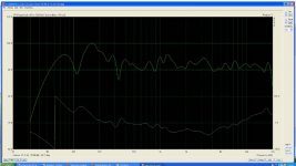
Here is an ARTA curve from an SH-50 at a meter in a cluttered room with a bare hardwood floor, no eq or correction, passive 3 way crossover. Anyway, the electrical crossovers are around 300Hz and 1100Hz, they are higher order and not traditional shapes but adapted to the requirements of the drivers and their coupling into the horn system..
In front you can’t detect there are different drivers or frequency ranges, even sticking your head in the horn. This design has been in service commercial sound for about 7 years now but only a few have found their way into homes yet..
Best,
Tom Danley
Danley Sound Labs
Fwiw, if you were to use an old TEF machine, it first identifies the time with a short ETC measurement, that measures and identifies the fixed delay. The next measurement the TDS produces the magnitude and acoustic phase. If one wants to see the mid range relative to the tweeter, you simply leave the time set by the hif driver. I have used various forms of the TEF machine since shortly after it came out and while it is limited in what it does, this (measuring the drivers magnitude and phase) it does better than anything else I have used.
In fact, if you guys haven’t looked at Richard Heyser’s work, you might find it interesting. Search up his paper on “determination of loudspeaker arrival times” or on Time Delay Spectrometry. The man was brilliant, an underappreciated audio pioneer, I have some of his work and I still shudder thinking he understood it and thought of it back then.
I met him at an aes dinner a couple years before he died. He was the kind of person that appeared to have a computer in his head and also talked about it in a way that I understood most of at least for some moments afterward. No kidding he and his machine had a strong impact on my loudspeaker life.
GDO, in fact one can make a multiway speaker that behaves like a point source, in fact you can make one that has no phase shift from a crossover and no lobes and nulls when driver interact as well so it really looks like a single driver. They have to occupy the same moment in time, they have to be close enough together to add into and radiates as one source, it’s just hard to do the normal way..
Here is an ARTA curve from an SH-50 at a meter in a cluttered room with a bare hardwood floor, no eq or correction, passive 3 way crossover. Anyway, the electrical crossovers are around 300Hz and 1100Hz, they are higher order and not traditional shapes but adapted to the requirements of the drivers and their coupling into the horn system..
In front you can’t detect there are different drivers or frequency ranges, even sticking your head in the horn. This design has been in service commercial sound for about 7 years now but only a few have found their way into homes yet..
Best,
Tom Danley
Danley Sound Labs
Attachments
Wow, this is really impressive. I had heard of these, but never reallly paid attention to what's achieved. I have an ongoing project of a Horbach Keele array with Acourate, but now the idea of building a Unity horn with a linear phase xover is even more appealing. Maybe i could get from such an arrangement a result similar to a Synergy horn...+ delay...
Gentlemen
If you check the free test signal on my website you will find the spectrum and howto test with it . I developed this test for Altec 605As to optimize the low freq delay on a passive XO design. The test signal could be used with any multi way system. Play the test signal and turn on/off one the drivers ( LF, HF ) while observing the acoustic signal with a mic and scope.
http://web.me.com/donaldpatten
The ARTA manual has this to say about it: "Theoretically, the averaging technique, from a dual channel system, can be applied in a single channel system, but due to the limitation of the Windows sound driver, which does not keep the synchronicity between the signal playback and recording, only the time domain synchronous averaging can be applied. The phase response can't be estimated with an absolute accuracy."
So if we use ASIO we can overcome this limitation and use Single Channel FFT mode or OS still makes its "corrections"? This isn't clear at least not from the manual.
- Status
- This old topic is closed. If you want to reopen this topic, contact a moderator using the "Report Post" button.
- Home
- Loudspeakers
- Multi-Way
- Measuring driver acoustic offset using excess group delay ?